Optical film

An optical film and optical technology, applied in the field of optical film, can solve the problems of impossible to expect light scattering effect, increased work difficulty, limited refraction direction, etc., to avoid optical coupling phenomenon, eliminate ripples, and improve productivity.

Active Publication Date: 2007-05-09
LMS SUZHOU MATERIALS CO LTD
View PDF0 Cites 6 Cited by
  • Summary
  • Abstract
  • Description
  • Claims
  • Application Information

AI Technical Summary

Problems solved by technology

[0006] Further, in the prior art, two optical films 201 and 201b are installed so that their prism patterns 211a and 211b cross each other, even if the direction in which light is collected and refracted is enlarged, due to the structure of the triangular prism patterns 211a and 211b , the direction of light refraction is still limited
Therefore, there is a problem that a significant improvement in luminance cannot be expected
[0007] In addition, in the prior art, two optical films 201 and 201b are installed so that their prism patterns 211a and 211b cross each other, and it is impossible to expect a light scattering effect due to the limitation of the light refraction direction
Therefore, there is a disadvantage that even if particles or scratches are generated between the optical films 201a and 201b during the manufacturing process, they cannot be removed visually.
Thus, there is a problem of reduced productivity due to the increased percentage of defects and difficulty of work

Method used


Image

  • Optical film
  • Optical film
  • Optical film

Examples


Embodiment Construction

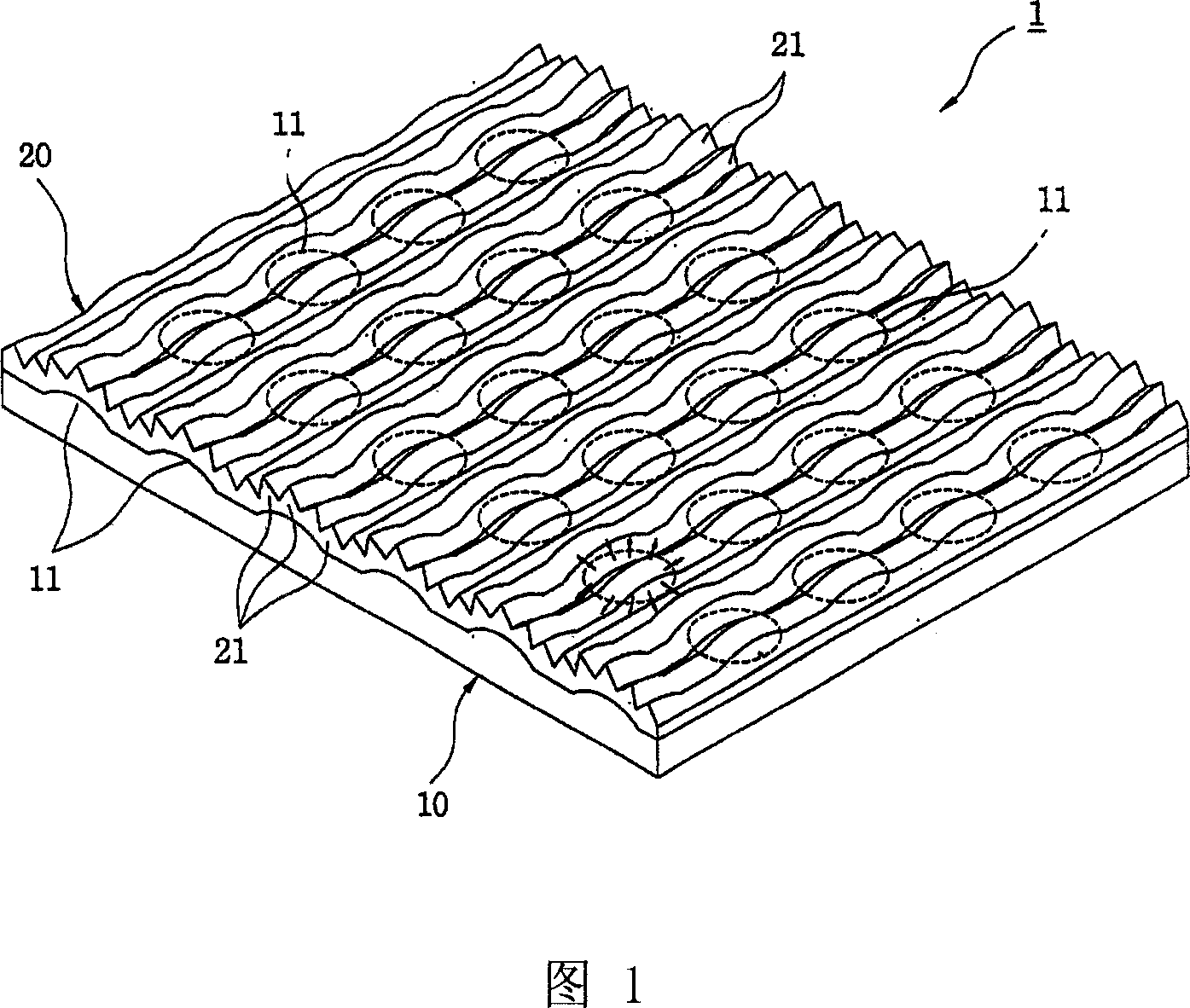
[0030] Hereinafter, the present invention will be described in detail with reference to the accompanying drawings. It should be noted that the optical films shown in the drawings are exaggerated for convenience of description.

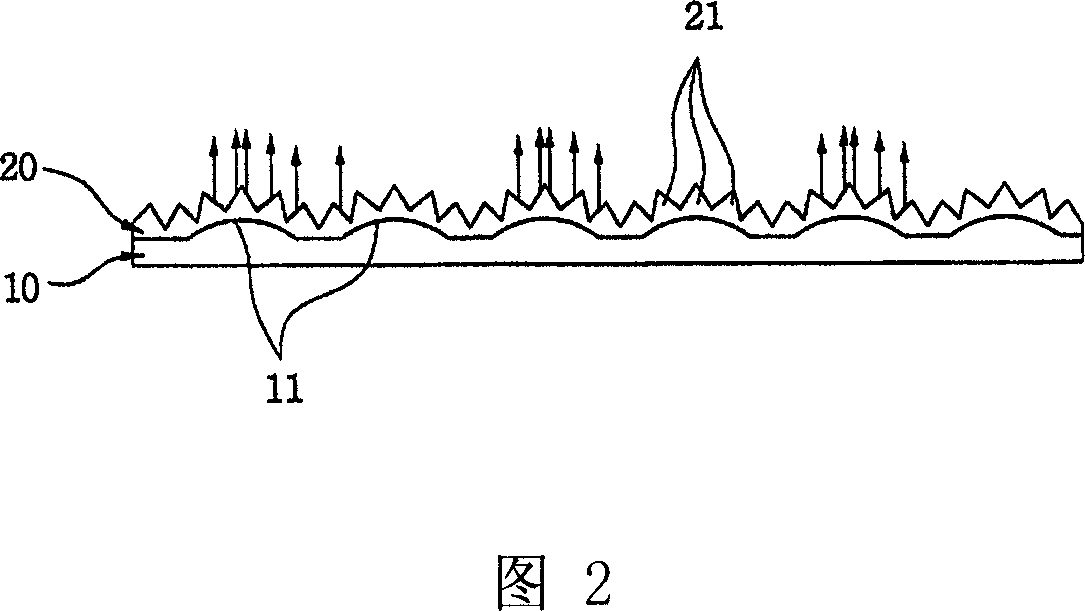
[0031] FIG. 1 is a perspective view of an optical film according to a first embodiment of the present invention, and FIG. 2 is a cross-sectional view of the optical film shown in FIG. 1 . As shown in the figure, the optical film 1 of the present embodiment includes a first refraction portion 10 having a plurality of first optical lens patterns 11 for collecting and diverging light emitted from a light source 105 at a predetermined angle. And incident on the first refraction part 10; And there is the second refraction part 20 of a plurality of second optical patterns 21, and this second optical figure collects the light that is diverged by the first refraction part 10, and the light that collects is vertically transmitted to Panel 107.

[0032] As sho...


PUM


Abstract

The present invention relates to an optical film. The optical film comprises a first refraction portion having a plurality of first optical lens patterns that have optical sections for controlling light and are distributed at a predetermined interval in the form of embossment; and a second refraction portion having a plurality of second optical patterns that have optical sections and are arranged linearly at a predetermined interval and formed along patterns surfaces of the first optical lens patterns. Accordingly, there is provided an optical film in which high brightness can be achieved at a wide viewing angle, the wet-out phenomenon can be avoided, and productivity can be improved.

Description

technical field [0001] The present invention relates to an optical film, in particular to an optical film with an improved optical pattern structure for collecting and refracting light. Background technique [0002] As shown in FIG. 12, a backlight unit 100 provided in a display device such as a TFT-LCD monitor for a mobile phone or an LCD includes an optical film 101 by collecting and refracting light emitted from a light source 105, and An image is displayed on panel 107 by making refracted light incident on panel 107 . [0003] A conventional optical film 101 for collecting and refracting light in a backlight unit has a structure as shown in FIG. 13, in which a plurality of prism patterns 111 having triangular cross-sections are linearly arranged. Since such a conventional optical film 101 with the prism pattern 111 has limitations in the direction of collecting and refracting light, there is a disadvantage that the brightness deteriorates significantly when the viewing ...

Claims


Application Information

Patent Timeline
Patent Type & Authority Applications(China)
IPC IPC(8): G02F1/1335G02B3/00G02B5/02G02B5/04G02B5/18
CPCG02F1/133504G02B3/0056G02B5/0221G02B3/0031G02B5/045G02B5/0257G02B5/021G02B1/10G02B5/0278G02F1/1335
Inventor 罗羽柱沈容植
Owner LMS SUZHOU MATERIALS CO LTD
Why Eureka
Try Eureka