Power converter controlled capacitor circuits and control method thereof

A technology of capacitors and controllers, applied in battery circuit devices, current collectors, circuit devices, etc.

Pending Publication Date: 2020-10-30
QUEENS UNIV OF KINGSTON
View PDF0 Cites 4 Cited by
  • Summary
  • Abstract
  • Description
  • Claims
  • Application Information

AI Technical Summary

Problems solved by technology

In summary, if film capacitors are used to improve the reliability of battery chargers, their volume in the power supply will be 11 times larger than that of electrolytic capacitors, which is unacceptable in practical applications

Method used


Image

  • Power converter controlled capacitor circuits and control method thereof
  • Power converter controlled capacitor circuits and control method thereof
  • Power converter controlled capacitor circuits and control method thereof

Examples


Embodiment example

[0138] Figure 14 Shown is a detailed circuit implementation of one embodiment of the invention. Such as Figure 14 As shown, a full bridge inverter is used as the power converter in the power control capacitor circuit 140 of the Boost converter. The output terminal of the full bridge inverter (for output voltage Vaux) is connected in series with the output capacitor Cout and then connected to the load Rload. The full-bridge inverter generates a voltage Vaux to offset the AC component of the voltage Vac1, thereby generating only a DC voltage across the load Rload. It should be noted that the capacitor Ca is part of the input LC filter of the full bridge inverter. The value of the capacitor Ca depends on the switching frequency, and the value of Ca does not depend on the low frequency component to be compensated by Vaux. The value of Ca is smaller than the value of the output capacitor Cout in most cases.

[0139] The input voltage Vin_aux of the full bridge inverter can be...


PUM


Abstract

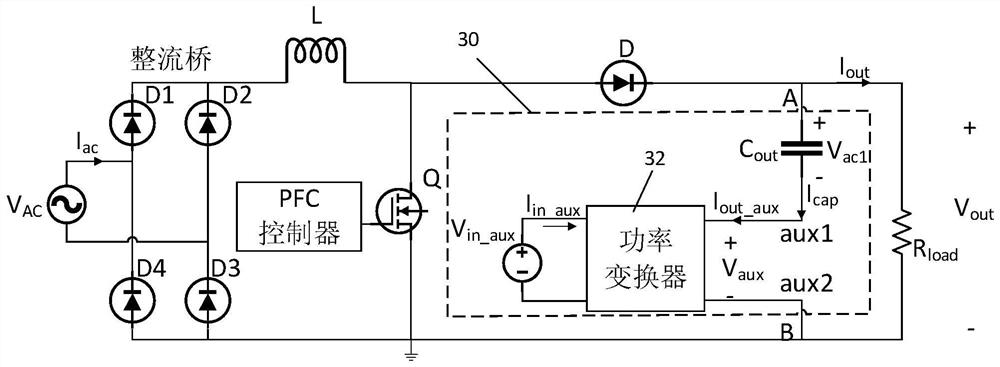
The invention discloses a power converter controlled series circuit and a control method thereof and a power system. The series circuit comprises: a capacitor having a first port A and a second port;a power converter, a first output port of the power converter being connected to a second port of the capacitor, a second output port of the power converter being a port B, and the power converter being used for outputting an auxiliary voltage; and a controller used for controlling the power converter to output auxiliary voltage according to the selected function; wherein the series circuit can beexpressed as an equivalent capacitor, inductor or impedor according to the selected function. The auxiliary voltage can basically eliminate low-frequency alternating-current voltage ripples at the two ends of the capacitor, so that basically pure direct-current output voltage is output to a load.

Description

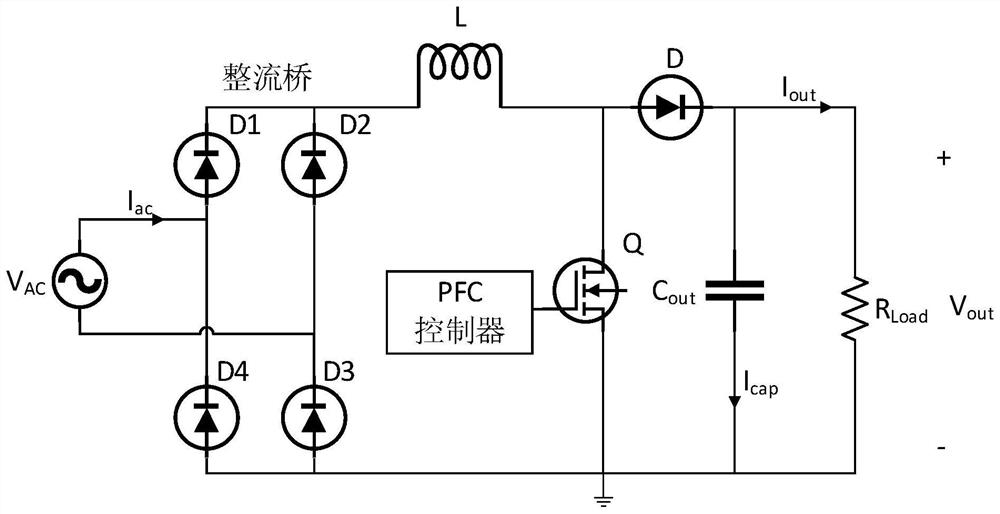
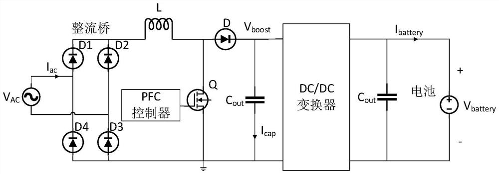
technical field [0001] The present invention relates to the field of AC-DC power converters, and more specifically, the present invention relates to a circuit and method for weakening or eliminating low-frequency AC ripples in the DC output of the AC-DC converter. Background technique [0002] Single-phase AC-DC power converters with power factor correction (PFC) are widely used in the power supply industry. As shown in Figure 1, this type of power supply most often uses a boost converter (such as a Boost converter) to implement power factor correction. When implementing power factor correction, the waveform of the input current of the Boost converter (before the diode rectifier bridge) is a sine wave with the same phase as the input AC voltage. Therefore, as shown in Figure 1, the output voltage Vout of the Boost converter contains a voltage ripple component of twice the power frequency (100Hz in Europe and Asia, and 120Hz in North America). The amplitude (or peak-to-peak ...

Claims


Application Information

Patent Timeline
IPC IPC(8): H02M1/14B60L53/30H02J7/02H02M1/42H02M7/04
CPCH02M1/14H02M1/15H02M1/42H02M1/4225H02J7/02H02J3/1864B60L53/22B60L2210/30H02J2310/48Y02T10/72Y02T10/70Y02T10/92Y02T10/7072Y02T90/14Y02T90/12H02J3/322H02J2310/22Y02B70/10B60L53/60B60L2210/10H02M1/143H02M1/4208H02M3/335
Inventor 刘雁飞
Owner QUEENS UNIV OF KINGSTON
Why Eureka
Try Eureka