
Speaker having a transparent panel

a technology of transparent panels and speakers, applied in the field of speakers having transparent panels, can solve the problems of unaddressed need in the industry, and achieve the effect of minimizing dampening qualities and minimizing bending of portions

Inactive Publication Date: 2005-07-14
BROOKSTONE PURCHASING
View PDF14 Cites 19 Cited by
  • Summary
  • Abstract
  • Description
  • Claims
  • Application Information

AI Technical Summary

Benefits of technology

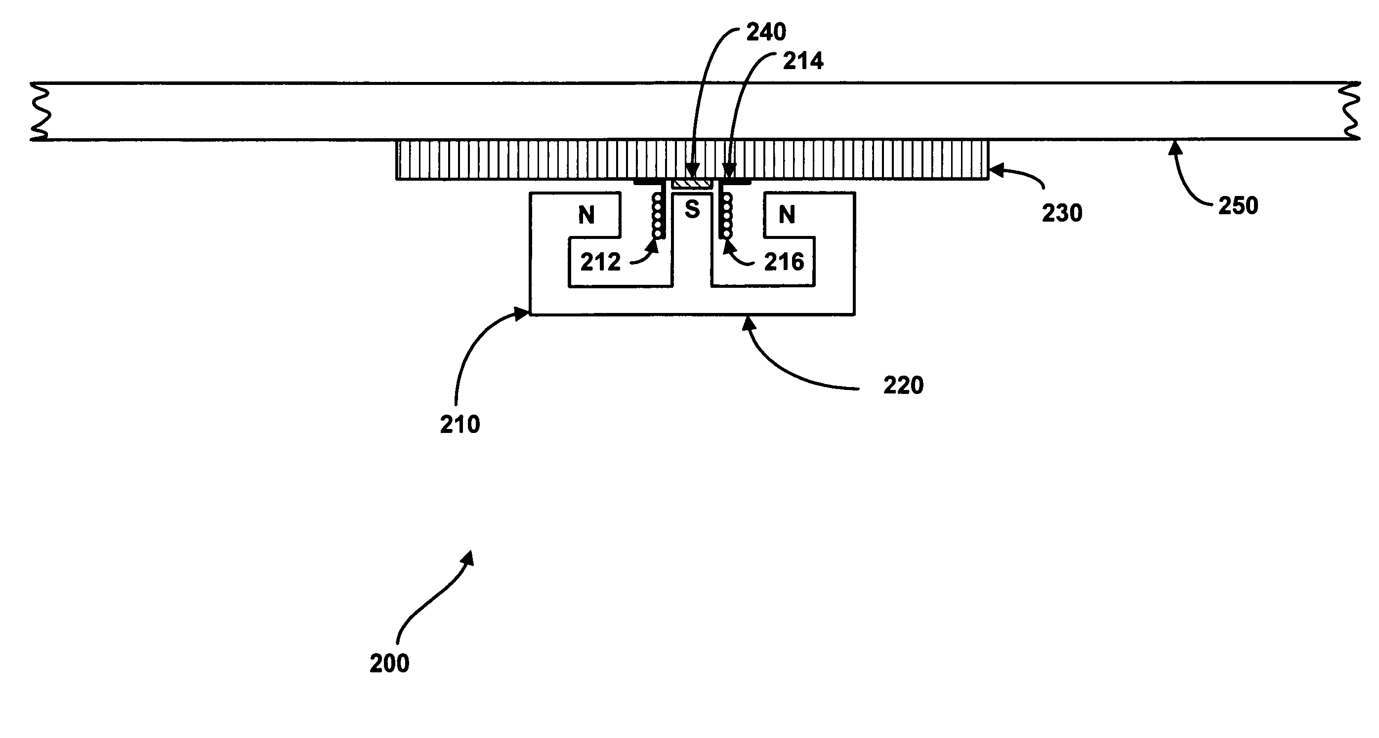
[0006] Embodiments of the present invention provide a speaker having a transparent sound panel. Briefly described, in architecture, one embodiment of the speaker, among others, can be implemented as follows. The speaker contains a transparent sound panel and an exciter connected to the transparent sound panel for converting electrical energy received by the exciter, into vibrations that are transmitted to the transparent sound panel, resulting in the transparent sound panel transmitting sound. The speaker also contains a stiff panel located between the exciter and the transparent sound panel, where the stiff panel minimizes dampening qualities associated with material utilized to fabricate the transparent sound panel and minimizes bending of the portion of the transparent sound panel that is in contact with the stiff panel. In addition, a dampening pad is located within the exciter for absorbing a portion of excessive mid-high frequency vibrations emanating from the exciter prior to transmission to the transparent sound panel.
[0007] The present invention can also be viewed as providing methods for transmitting sound via a transparent sound panel. In this regard, one embodiment of such a method, among others, can be broadly summarized by the following steps: converting electrical energy into mechanical energy; absorbing a portion of excessive mid-high frequency vibrations prior to transmission to the transparent sound panel; and minimizing restriction of sound wave traversal throughout the transparent sound panel, prior to the sound wave traversal throughout the transparent sound panel.

Problems solved by technology

Unfortunately, while speakers may be made smaller in size so as not to have a large visual presence, they are still visually apparent, predominantly due to the speaker cone or panel.
Thus, a heretofore unaddressed need exists in the industry to address the aforementioned deficiencies and inadequacies.

Method used


Image

  • Speaker having a transparent panel
  • Speaker having a transparent panel
  • Speaker having a transparent panel

Examples


Embodiment Construction

[0015] The present invention provides a speaker having a transparent sound panel. It should be noted that, while the following describes different examples of material that may be used to provide the speaker having a transparent sound panel, one having ordinary skill in the art would appreciate that other material that would provide the transparent sound panel may be utilized. In addition, it should be noted that the present speaker may alternatively use the same material as mentioned herein, however with the material being colored or having a visual haze or non-clear portion. In addition, the material may be frosted or have a design painted, stained, or manufactured thereon.

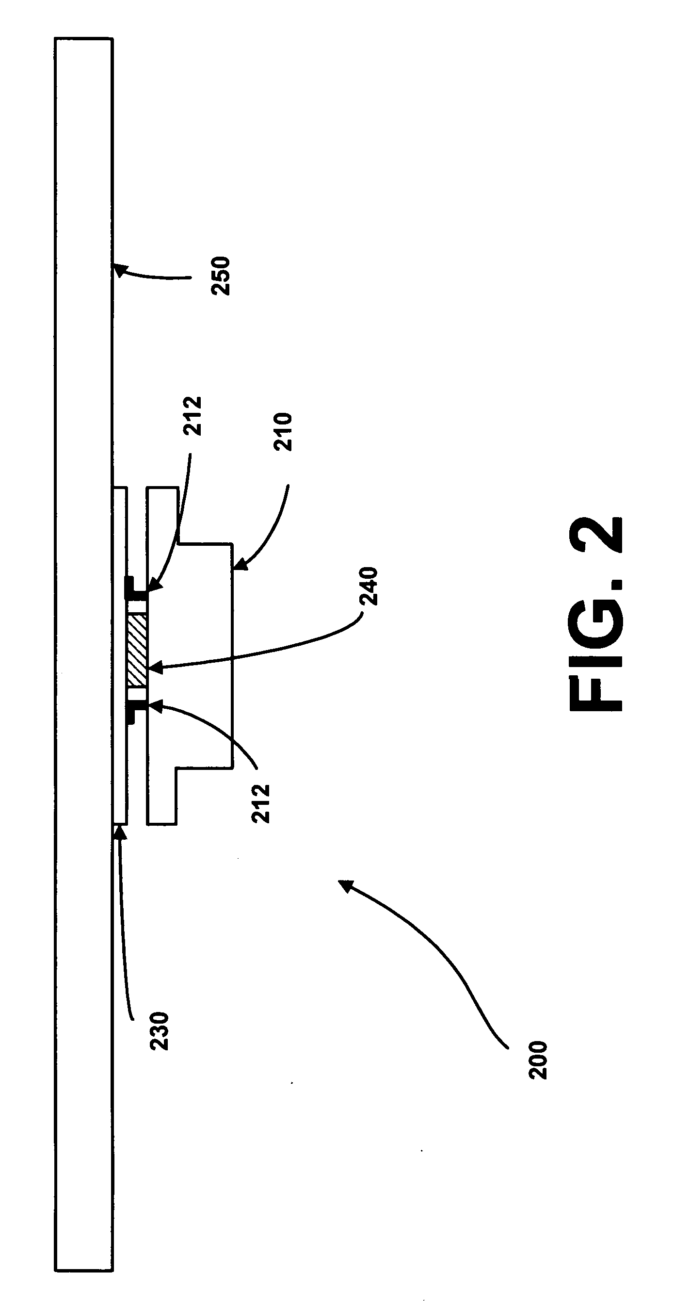
[0016]FIG. 2 is a schematic diagram providing a side view of the present speaker 200 having a transparent sound panel 250, in accordance with a first exemplary embodiment of the invention. As is shown by FIG. 2, the speaker 200 contains an exciter 210 and a transparent sound panel 250. In addition, a stiff pane...


PUM


Abstract

A speaker having a transparent sound panel and an exciter connected to the transparent sound panel for converting electrical energy received by the exciter, into vibrations that are transmitted to the transparent sound panel, resulting in the transparent sound panel transmitting sound. The speaker also contains a stiff panel located between the exciter and the transparent sound panel, where the stiff panel minimizes dampening qualities associated with material utilized to fabricate the transparent sound panel and minimizes bending of the portion of the transparent sound panel that is in contact with the stiff panel. In addition, a dampening pad is located within the exciter for absorbing a portion of excessive mid-high frequency vibrations emanating from the exciter prior to transmission to the transparent sound panel.

Description

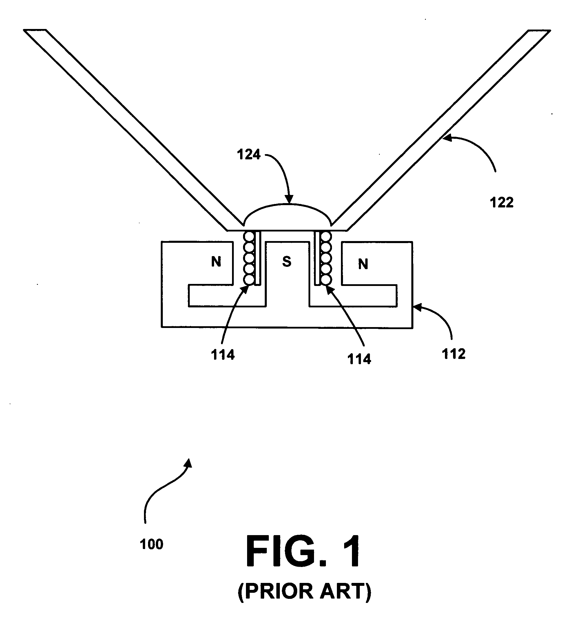
FIELD OF THE INVENTION [0001] The present invention is generally related to audio speakers, and more particularly is related to a speaker having a transparent sound panel. BACKGROUND OF THE INVENTION [0002] Audio speakers have changed throughout time due to technological advancements and consumer perception of aesthetic appeal. Such technological advancements have led, for instance, to a decrease in the size of audio speakers and an increase in audio performance. As an example, while loud speakers still typically contain the same fundamental parts, namely, an electro-mechanical transducer (hereafter referred to as an “exciter”) and a diaphragm or panel, certain loud speakers have become smaller in size and have increased in sound quality. In addition, certain loud speakers have changed in shape and color for aesthetic appeal. [0003]FIG. 1 is a schematic diagram illustrating cross-sectional view of a typical loudspeaker 100. As is shown by FIG. 1, the loudspeaker 100 contains an exci...

Claims


Application Information

Patent Timeline
Patent Type & Authority Applications(United States)
IPC IPC(8): H04R1/00H04R7/04H04R9/06H04R11/02
CPCH04R9/06H04R7/045
Inventor HARRIS, KENNETH DAVID JR.LI, VIAN W.Y.TRZEPACZ, TIMOTHY L.
Owner BROOKSTONE PURCHASING
Learn More