Optical pickup device and diffractive optical element

a pickup device and optical element technology, applied in the field of optical pickup devices, can solve the problems of small curvature radius of the attached surface, narrow pitch, difficult machining, etc., and achieve the effect of ensuring downward compatibility and less fluctuations in spherical aberrations

Active Publication Date: 2005-07-21
JVC KENWOOD CORP A CORP OF JAPAN
View PDF0 Cites 16 Cited by
  • Summary
  • Abstract
  • Description
  • Claims
  • Application Information

AI Technical Summary

Benefits of technology

[0031] Thus, there has been demanded an optical pickup device and a diffractive optical element which can assure the downward compatibility between a first optical recording medium (e.g., a Blu-ray Disc) whose recording density is an extra-high density and a second optical recording medium (e.g., a DVD) whose recording density is lower than that of the first light recording medium by using one objective lens in order to record or reproduce information, have less fluctuations in spherical aberrations when a wavelength change occurs, lead the design of a chromatic aberration correction element which is simultaneously used for the Blu-ray Disc to facilitate manufacture, and involve no increase in the number of elements.
[0035] According to the optical pickup device of the present invention, particularly, when a wavelength having the same value as the reference wavelength λ1 of the first later light is set to the designed wavelength λ, since the diffractive optical element has: an inner circular side tiered diffraction pattern portion, in which a plurality of tiers in which a height of each tier is set to approximately 2λ-fold of the designed wavelength λ is determined as one set and a plurality of such sets are repeated, being formed into an annular shape in the inner circular area having a predetermined diameter for the correction of a spherical aberration generated due to a difference in substrate thickness between the first and second optical recording mediums centering on the central point through which the optical axis runs while gradually changing a pitch of the tiers in the radial direction toward the outer circular side; and the outer circular side tiered diffraction pattern portion intended to improve a chromatic aberration with respect to the first laser light by forming in an annular shape in the outer circular area outside the inner circular side tiered diffraction pattern portion a plurality of tiers by setting a height of each tier to an approximately mλ-fold (where m is a natural number which does not include 0) of the designed wavelength λ or by setting the same while changing a value of m for each tier, a spherical aberration with respect to the second laser light can be corrected by the inner peripheral tiered diffraction pattern portion, and a chromatic aberration can be corrected with respect to the first laser light by the outer circular side tiered diffraction pattern portion. Therefore, information can be excellently recorded on or reproduced from the first optical recording medium and the second optical recording medium, and the design of the chromatic aberration correction element can be led to facilitation of manufacture.
[0037] According to the diffractive optical element of the present invention, like the first invention concerning the optical pickup device mentioned above, information can be excellently recorded on or reproduced from the first optical recording medium and the second optical recording medium, and the design of the chromatic aberration correction element can be led to facilitation of manufacture.
[0039] According to the diffractive optical element of the present invention, like the second invention concerning the optical pickup device mentioned above, information can be excellently recorded on or reproduced from the first optical recording medium and the second optical recording medium, and the design of the chromatic aberration correction element can be led to facilitation of manufacture.

Problems solved by technology

Additionally, since the triplet 142 which serves as the chromatic aberration correcting means must be designed in such a manner that it can correct an epaxial chromatic aberration excessively in the entire optics, a curvature radius of the attached surface becomes small, and machining is difficult.
Additionally, when the analog blaze 151Ba (or the tiered blaze) is formed to the Fresnel lens 151B in the beam expander 151, a pitch becomes narrow, and machining is thereby difficult.

Method used


Image

  • Optical pickup device and diffractive optical element
  • Optical pickup device and diffractive optical element
  • Optical pickup device and diffractive optical element

Examples


embodiment 1

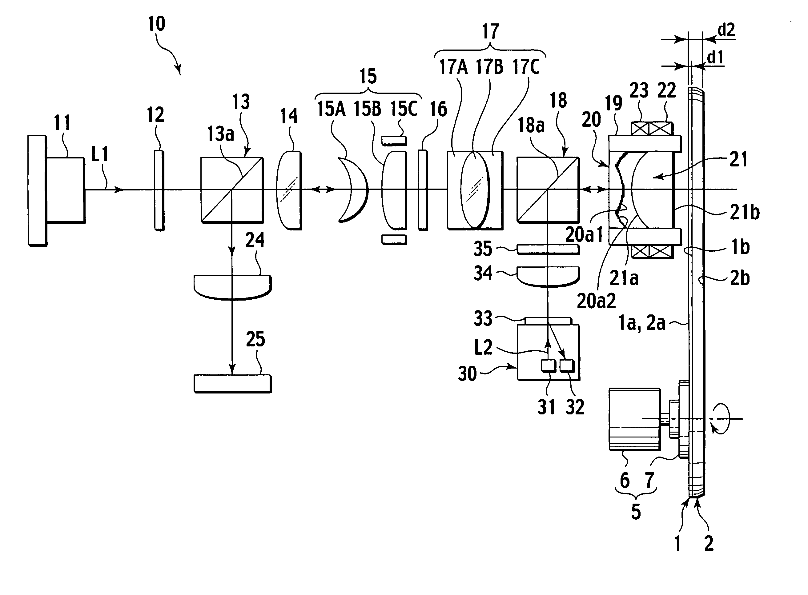
[0073]FIG. 7 is a diagram showing the whole constitution of an optical pickup device of Embodiment 1 according to the present invention.

[0074] As shown in FIG. 7, an optical pickup device 10 of Embodiment 1 according to the present invention was developed to enable selective application of a first optical recording medium 1 which records or reproduces an information signal at an extra-high density on or from a signal surface 1b with a small substrate:thickness by using a first laser light L1 whose reference wavelength λ1 is not more than 450 nm, a second optical recording medium 2 which records or reproduces an information signal at a high density on or from a signal surface 2b whose substrate thickness is larger than that of the signal surface 1b of the first optical recording medium 1 by using a second laser light L2 whose reference wavelength λ2 is approximately 650 nm longer than the reference wavelength λ1 of the first laser light L1, and a combined optical recording medium in...

embodiment 2

[0192]FIG. 24 is a view showing an entire structure of an optical pickup device of Embodiment 2 according to the present invention. FIGS. 25A and 25B are a general view and an enlarged view of an X portion illustrating a diffractive optical element in Embodiment 2 according to the present invention. FIG. 26 is a view showing Modification 1 obtained by partially modifying the diffractive optical element in Embodiment 2 according to the present invention. FIG. 27 is a view showing Modification 2 obtained by partially modifying the diffractive optical element in Embodiment 2 according to the present invention.

[0193] As shown in FIG. 24, an optical pickup device 10′ of Embodiment 2 is configured by substituting the diffractive optical element 20 in the optical pickup device 10 in Embodiment 1 described with reference to FIG. 7 with a diffractive optical element 20′ having a different shape, and a description will be mainly given on a difference from Embodiment 1.

[0194] That is, as sho...


PUM

PropertyMeasurementUnit
wavelengthaaaaaaaaaa
diameteraaaaaaaaaa
wavelengthaaaaaaaaaa

Abstract

When a wavelength having the same value as a reference wavelength Al of a first laser light is set to a designed wavelength λ, a diffractive optical element has: an inner circular side irregular diffraction pattern portion, in which a plurality of irregular portions in which a height of a convex portion is set to approximately 1λ-fold of the designed wavelength λ with respect to a concave portion are repeated, being formed in an annular shape in an inner circular area having a predetermined diameter for the correction of a spherical aberration generated due to a difference in substrate thickness between first and second optical recording mediums centering on a central point through which an optical axis runs while gradually changing a pitch of the irregular portions in a radial direction toward the outer circular side; and an outer circular side tiered diffraction pattern portion which is intended to improve a chromatic aberration with respect to the first laser light by forming in an annular shape in an outer circular area outside the inner circular side irregular diffraction pattern portion a plurality of tiers by setting a height of each tier to approximately mλ-fold (where m is a natural number which does not include 0) of the designed wavelength λ or by setting the same while changing a value of m for each tier.

Description

BACKGROUND OF THE INVENTION [0001] 1. Field of the Invention [0002] The present invention relates to an optical pickup device comprising at least: a chromatic aberration correction element which corrects a chromatic aberration with respect to a first laser light; first and second laser light separating means for separating the first laser light and a second laser light from each other; a diffractive optical element which corrects a spherical aberration generated due to a difference in substrate thickness between first and second optical recording mediums; and an objective lens whose numerical aperture (NA) is not less than 0.75, and to a diffractive optical element when selectively recording or reproducing the first optical recording medium and the second optical recording medium by using the first laser light having a short wavelength for the first optical recording medium having a small substrate thickness and the second laser light having a wavelength longer than that of the firs...

Claims


Application Information

Patent Timeline
Patent Type & Authority Applications(United States)
IPC IPC(8): G11B7/00G11B7/125G11B7/135G11B7/1353G11B7/1367G11B7/1392
CPCG11B7/1353G11B2007/0006G11B7/13922G11B7/1367
Inventor ITONAGA, MAKOTO
Owner JVC KENWOOD CORP A CORP OF JAPAN
Why Eureka
Try Eureka