Optical pickup device

a pickup device and optical technology, applied in the field of optical pickup devices, can solve the problems of small curvature radius of the attached surface, narrow pitch, difficult machining, etc., and achieve the effect of less fluctuation of spherical aberrations

Active Publication Date: 2007-11-27
JVC KENWOOD CORP
View PDF12 Cites 8 Cited by
  • Summary
  • Abstract
  • Description
  • Claims
  • Application Information

AI Technical Summary

Benefits of technology

[0029]Thus, there has been demanded an optical pickup device which can assure the downward compatibility between a first optical recording medium (e.g., a Blu-ray Disc) whose recording density is an extra-high density and a second optical recording medium (e.g., a DVD) whose recording density is lower than that of the first light recording medium by using one objective lens in order to record or reproduce information, has less fluctuations in spherical aberrations when a wavelength change occurs, leads the design of a chromatic aberration correction element which is simultaneously used for the Blu-ray Disc to facilitate manufacture, and involves no increase in the number of elements.

Problems solved by technology

Additionally, since the triplet 142 which serves as the chromatic aberration correcting means must be designed in such a manner that it can correct an epaxial chromatic aberration excessively in the entire optics, a curvature radius of the attached surface becomes small, and machining is difficult.
Additionally, when the analog blaze 151Ba (or the tiered blaze) is formed to the Fresnel lens 151B in the beam expander 151, a pitch becomes narrow, and machining is thereby difficult.

Method used


Image

  • Optical pickup device
  • Optical pickup device
  • Optical pickup device

Examples


Embodiment Construction

[0064]An embodiment of an optical pickup device according to the present invention will now be described in detail hereinafter with reference to FIGS. 6 to 22.

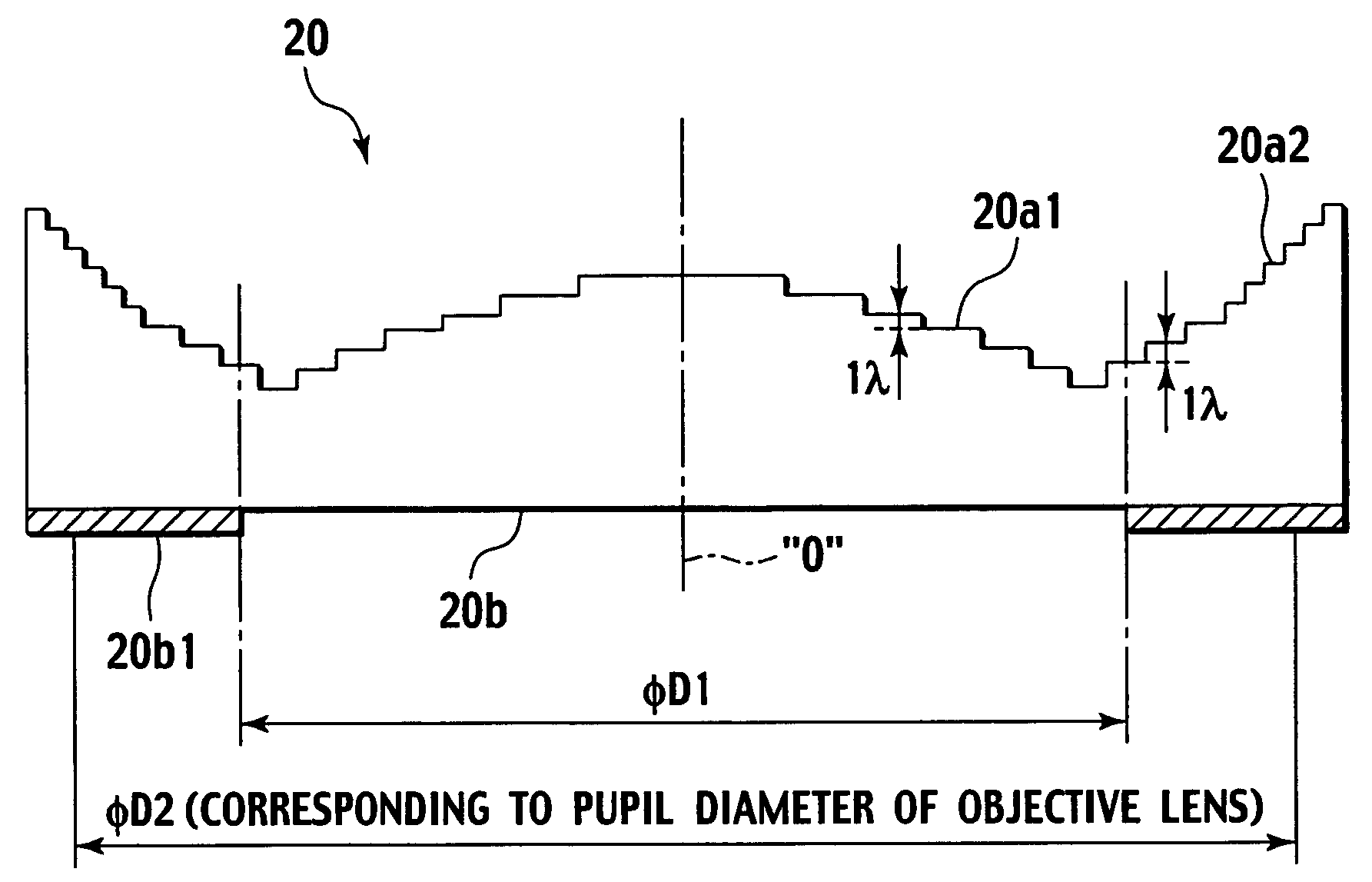
[0065]An optical pickup device according to the present invention is characterized in that, when assuring downward compatibility between a first optical recording medium (e.g., a Blu-ray Disc) whose recording density is an extra-high density and a second optical recording medium (e.g., a DVD) whose recording density is lower than that of the first optical recording medium by using one objective lens in order to record or reproduce information, the optical pickup device comprises at least: an objective lens which is designed to be compatible with the first optical recording medium based on next-generation optical disc standards and has a numerical aperture (NA) of 0.75 or above; a chromatic aberration correction element which corrects a chromatic aberration with respect to the first optical recording medium; and a phase shift e...


PUM

PropertyMeasurementUnit
wavelengthaaaaaaaaaa
diameteraaaaaaaaaa
wavelengthaaaaaaaaaa

Abstract

First and second phase function curves are respectively obtained based on first and second phase functions with a wavelength having the same value as a reference wavelength λ1 of a first laser light being determined as a designed wavelength λ, a phase shift element then has an inner circular side tiered phase difference pattern portion formed in annular shapes in an inner circular area on one surface thereof based on the first phase function curve and an outer circular side tiered phase difference pattern portion formed in annular shapes in an outer circular area outside the inner circular side tiered phase difference pattern portion based on the second phase function curve. A tier pitch of tiers of the inner circular side tiered phase difference pattern portion is set to a height corresponding to a phase difference of approximately 1λ and, on the other hand, a tier pitch of tiers of the outer circular side tiered phase difference pattern portion is set to a height corresponding to a phase difference of approximately mλ (where m is a natural number which does not include 0) or a height corresponding to a phase difference of approximately mλ by changing a value of m in accordance with each tier.

Description

BACKGROUND OF THE INVENTION[0001]1. Field of the Invention[0002]The present invention relates to an optical pickup device comprising at least: an objective lens whose numerical aperture (NA) is not less than 0.75; and a phase shift element which corrects a spherical aberration generated due to a difference in substrate thickness between first and second optical recording mediums when the objective lens is used in cases where the first and second optical recording mediums having different substrate thicknesses are selectively recorded or reproduced by using first and second laser lights having different wavelengths.[0003]2. Description of the Related Art[0004]In general, optical recording mediums such as a discoid optical disc or a card-shaped optical card are often used since they can record information signals of, e.g., video information, sound information or computer data on tracks spirally or concentrically formed on a transparent substrate with a high density, and access a desir...

Claims


Application Information

Patent Timeline
Patent Type & Authority Patents(United States)
IPC IPC(8): G11B7/00G02B5/18G11B7/125G11B7/1275G11B7/135G11B7/1392
CPCG11B7/1275G11B7/13922G11B2007/0006
Inventor ITONAGA, MAKOTO
Owner JVC KENWOOD CORP
Why Eureka
Try Eureka