Image forming apparatus

a technology of forming apparatus and fusing device, which is applied in the direction of electrographic process apparatus, instruments, optics, etc., can solve the problems of limited power supply from the commercial power supply to the fusing device, and achieve the effect of quick temperature ris

Inactive Publication Date: 2005-08-04
CANON KK
View PDF40 Cites 33 Cited by
  • Summary
  • Abstract
  • Description
  • Claims
  • Application Information

AI Technical Summary

Benefits of technology

[0020] The present invention fulfills the above-described and other needs by providing an image forming apparatus that can implement on-demand fusing with quick rise in temperature by using the upper current (power) limit of a commercial power supply more effectively. In exemplary embodiments, the image forming apparatus includes a rechargeable battery device capable of charging and discharging, and is designed such that a driven load other than the heating element of a fusing device can receive power a commercial power supply and / or the rechargeable battery device. When printing is to be executed, the commercial power supply and rechargeable battery device are controlled as power supply sources for the driven load. The power supplied from the commercial power supply to the fusing device is then limited to a limit level corresponding to the control result.

Problems solved by technology

The power supplied from the commercial power supply to the fusing device is then limited to a limit level corresponding to the control result.

Method used


Image

  • Image forming apparatus
  • Image forming apparatus
  • Image forming apparatus

Examples


first embodiment

[0124] In the first embodiment, the degree of change in power limit value must be determined in advance in consideration of variations in the load 460, changes over time, and the like in addition to the maximum power consumed by the load 460. In general, however, the power consumption of the load seldom reaches this maximum power consumption that can be estimated. In image forming operation, the power consumption of the load is sufficiently lower than the estimated maximum power consumption. If there is a different between the maximum power consumption and an actual power consumption, the different in power can be regarded as surplus power. Therefore, while a switch 463 is closed to supply power from a rechargeable battery device 455 to the load 460, the difference between the estimated maximum power consumption and the power actually consumed by the load 460 is calculated on the basis of the current detection result obtained by the current detection circuit 471. The power limit val...

fifth embodiment

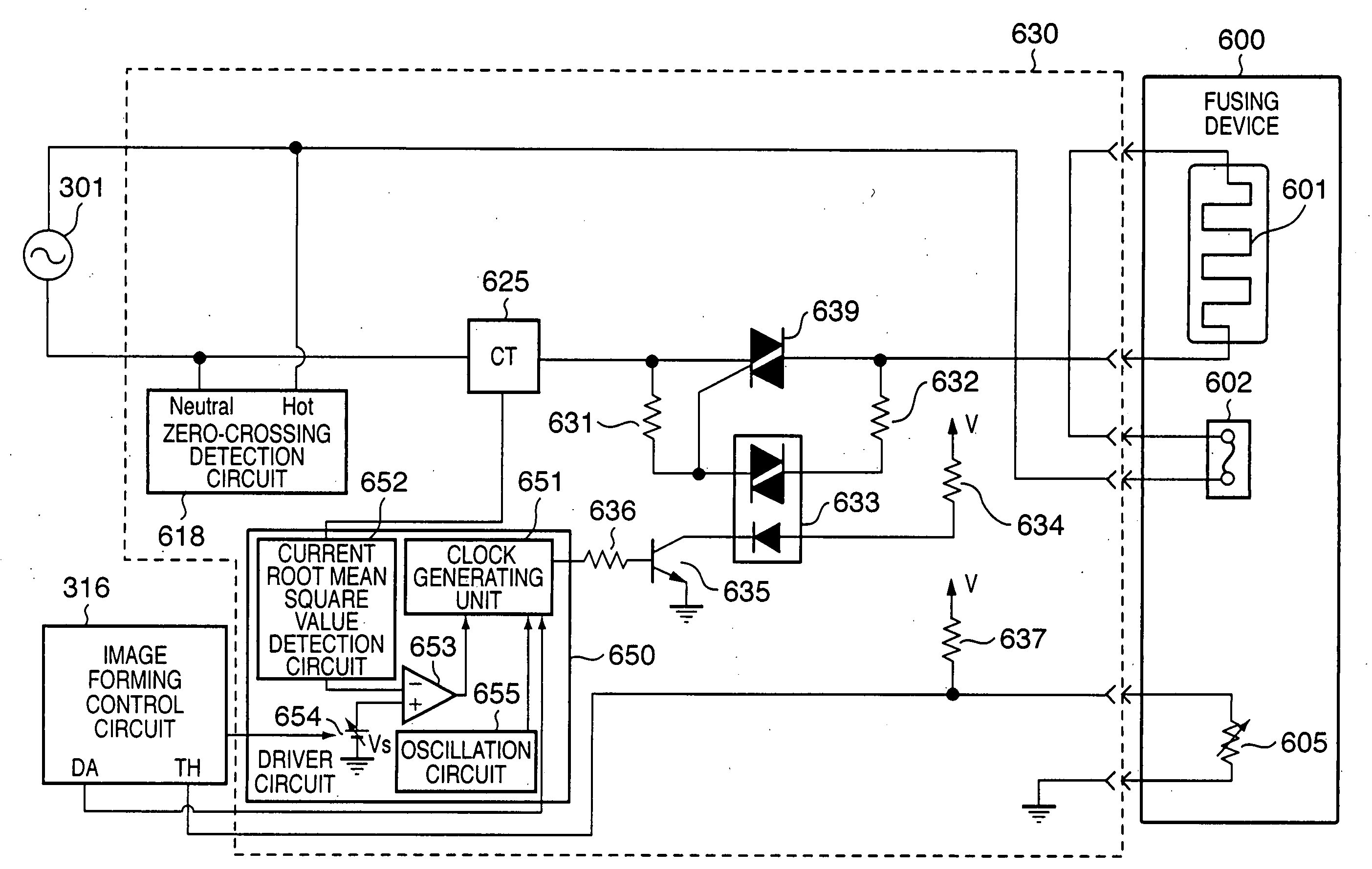
[0166] In each embodiment described above, the fusing device 23 of the electromagnetic induction heating system is used. However, fusing devices based on other systems can also be used. In the fifth embodiment, a fusing device based on a ceramic sheet heater system will be described.

[0167]FIG. 19 is a view showing the cross-sectional structure of a fusing device 600 based on the ceramic sheet heater system according to this embodiment.

[0168] Reference numeral 610 denotes a stay. The stay 610 is comprised of a main body portion 611 which has a U-shaped cross-section and supports a ceramic heater 640 in an exposed state and a pressurizing portion 613 which pressurizes the main body portion toward a pressurized roller 620 which faces the main body portion. In this case, the ceramic sheet heater may have a heating element located on the opposite side to the nip portion (to be described later) or on the nip portion side. Reference numeral 614 denotes a heat-resistant film (to be simply ...


PUM


Abstract

There is provided an image forming apparatus which can implement on-demand fusing with quick rise in temperature by using the upper current (power) limit of a commercial power supply more effectively. This image forming apparatus includes a rechargeable battery device capable of charging and discharging, and is designed such that a driven load other than the heating element of a fusing device can receive power a commercial power supply and/or the rechargeable battery device. When printing is to be executed, the commercial power supply and rechargeable battery device are controlled as power supply sources for the driven load. The power supplied from the commercial power supply to the fusing device is then limited to a limit level corresponding to the control result.

Description

FIELD OF THE INVENTION [0001] The present invention relates to an image forming apparatus and, more particularly, to an image forming apparatus using an electrophotographic process.BACKGROUND OF THE INVENTION [0002] An image forming apparatus using an electrophotographic process, e.g., a laser beam printer, comprising a fusing device which thermal-fuses a toner image formed on a printing medium (e.g., a printing sheet or OHP sheet). The heating systems which can be used for this fusing device include several types. Of these types, an electromagnetic induction heating system which induces a current in a fusing roller using a magnetic flux and generates heat using the resultant Joule heat, in particular, can directly cause the fusing roller to generate heat by using the generation of the induced current. This system is advantageous over a fusing unit based on a heated roller system using a halogen lamp as a heat source in terms of achieving a high-efficiency fusing process (see, for e...

Claims


Application Information

Patent Timeline
Patent Type & Authority Applications(United States)
IPC IPC(8): G03G15/00G03G15/20G03G21/00
CPCG03G2215/00983G03G2215/2035G03G15/80G03G15/2039
Inventor HANAMOTO, HIDETOSHIKOYAMA, SATORU
Owner CANON KK
Why Eureka
Try Eureka