Scanning probe microscopy inspection and modification system
What is Al technical title?
Al technical title is built by PatSnap Al team. It summarizes the technical point description of the patent document.
a microscopy and scanning probe technology, applied in the direction of electrostatic motors, electrical/magnetic measuring arrangements, record information storage, etc., can solve problems such as the defectiveness of the prob
Inactive Publication Date: 2005-08-11
TERRASPAN
View PDF99 Cites 38 Cited by
Summary
Abstract
Description
Claims
Application Information
AI Technical Summary
This helps you quickly interpret patents by identifying the three key elements:
Problems solved by technology
Method used
Benefits of technology
Problems solved by technology
A probe may be defective because of wear or because of fabrication errors.
Method used
Image
Click on the blue label to locate the original text in one second.
Reading with bidirectional positioning of images and text.
Examples
Embodiment Construction
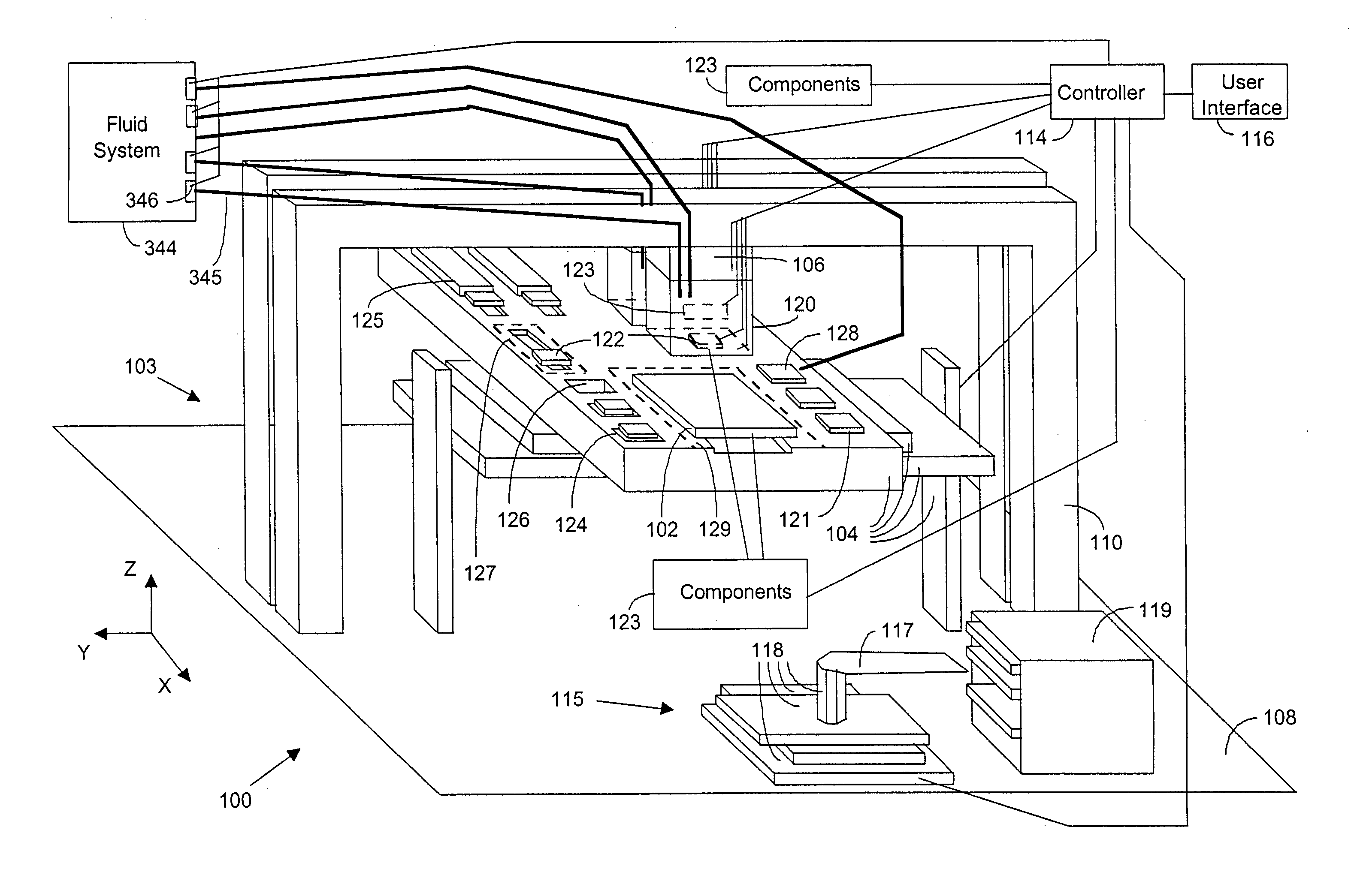
[0063] Referring to FIG. 1, there is shown an exemplary embodiment of an SPM (scanning probe microscopy) object inspection and / or modification system 100 which uses SPM technology and techniques in new and novel ways to inspect and / or modify an object 102. For example, as will be discussed throughout this document, the system can be used to perform tests, fabrication (i.e., manufacturing) steps, and / or repairs on semiconductor wafers and fabrication masks, lithographic structures (i.e., masters), and thin film magnetic read / write heads. Additionally, as will also be discussed throughout this document, the SPM system can also be used to analyze and / or alter biological or chemical samples.
[0064] The components of the SPM system 100 include a positioning system 103 that comprises a rough positioning apparatus 104, fine positioning apparatuses 106, a support table 108, and scanning head support structures 110. The rough positioning apparatus comprises a rough 3-D (i.e., three dimension...
PUM
Property
Measurement
Unit
thickness
aaaaa
aaaaa
temperature
aaaaa
aaaaa
thickness
aaaaa
aaaaa
Abstract
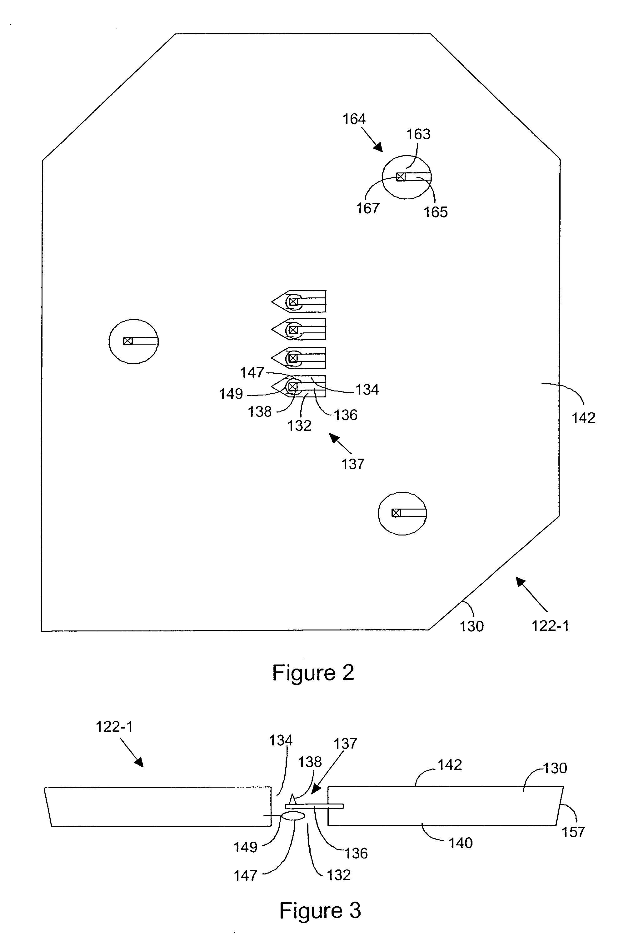
A scanning probe microscopy (SPM) inspection and / or modification system which uses SPM technology and techniques. The system includes various types of microstructured SPM probes for inspection and / or modification of the object. The components of the SPM system include microstructured calibration structures. A probe may be defective because of wear or because of fabrication errors. Various types of reference measurements of the calibration structure are made with the probe or vice versa to calibrate it. The components of the SPM system further include one or more tip machining structures. At these structures, material of the tips of the SPM probes may be machined by abrasively lapping and chemically lapping the material of the tip with the tip machining structures.
Description
CROSS-REFERENCES TO RELATED APPLICATIONS [0001] This application is a continuation of U.S. patent application Ser. No. 09 / 919,780, filed Jul. 31, 2001, which is a continuation of U.S. patent application Ser. No. 09 / 355,072, now U.S. Pat. No. 6,337,479, which is a National Phase filing of PCT Patent Application PCT / US98 / 01528, filed Jan. 21, 1998. [0002] PCT Patent Application No. PCT / US98 / 01528 is a continuation-in-part of U.S. patent application Ser. No. 08 / 906,602, filed Dec. 10, 1996, now U.S. Pat. No. 6,265,711, which is a file wrapper continuation of U.S. patent application Ser. No. 08 / 281,883, filed Jul. 28, 1994, now abandoned. [0003] PCT Patent Application No. PCT / US98 / 01528 is a continuation-in-part of U.S. patent application Ser. No. 08 / 885,014, filed Jul. 1, 1997, now U.S. Pat. No. 6,144,028, which is a continuation of U.S. patent application Ser. No. 08 / 412,380, filed Mar. 29, 1995, now abandoned, which is a continuation-in-part of U.S. patent application Ser. No. 08 / 281...
Claims
Application Information
Patent Timeline
Application Date:The date an application was filed.
Publication Date:The date a patent or application was officially published.
First Publication Date:The earliest publication date of a patent with the same application number.
Issue Date:Publication date of the patent grant document.
PCT Entry Date:The Entry date of PCT National Phase.
Estimated Expiry Date:The statutory expiry date of a patent right according to the Patent Law, and it is the longest term of protection that the patent right can achieve without the termination of the patent right due to other reasons(Term extension factor has been taken into account ).
Invalid Date:Actual expiry date is based on effective date or publication date of legal transaction data of invalid patent.
Patent Type & Authority Applications(United States)