Assembly of sashes for sliding glass doors

a technology for sliding glass doors and sashes, applied in the field of sashes, can solve problems such as unpractical construction

Inactive Publication Date: 2005-08-11
ORBECK DAVID +1
View PDF26 Cites 5 Cited by
  • Summary
  • Abstract
  • Description
  • Claims
  • Application Information

AI Technical Summary

Problems solved by technology

While the art dealing with such sashes has been well developed over many years, there has not been available a practical construction that enables one to apply one or more investitures adjacent the inside surface of sliding glass doors in such manner that they can be slid into or out of position.

Method used


Image

  • Assembly of sashes for sliding glass doors
  • Assembly of sashes for sliding glass doors
  • Assembly of sashes for sliding glass doors

Examples


Embodiment Construction

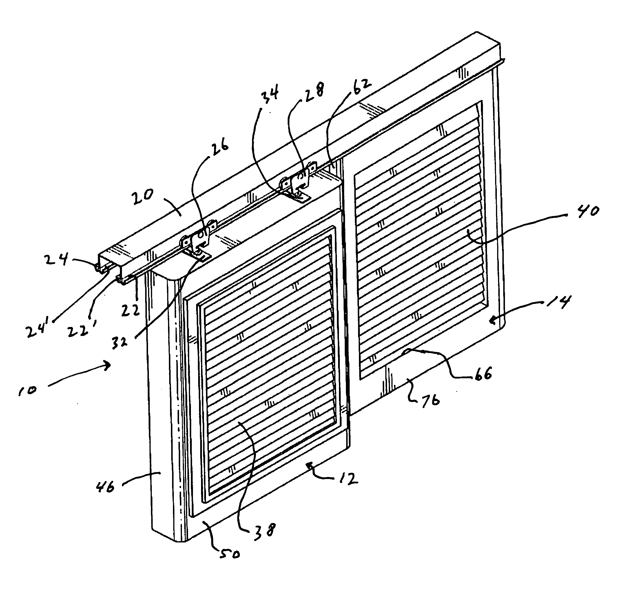
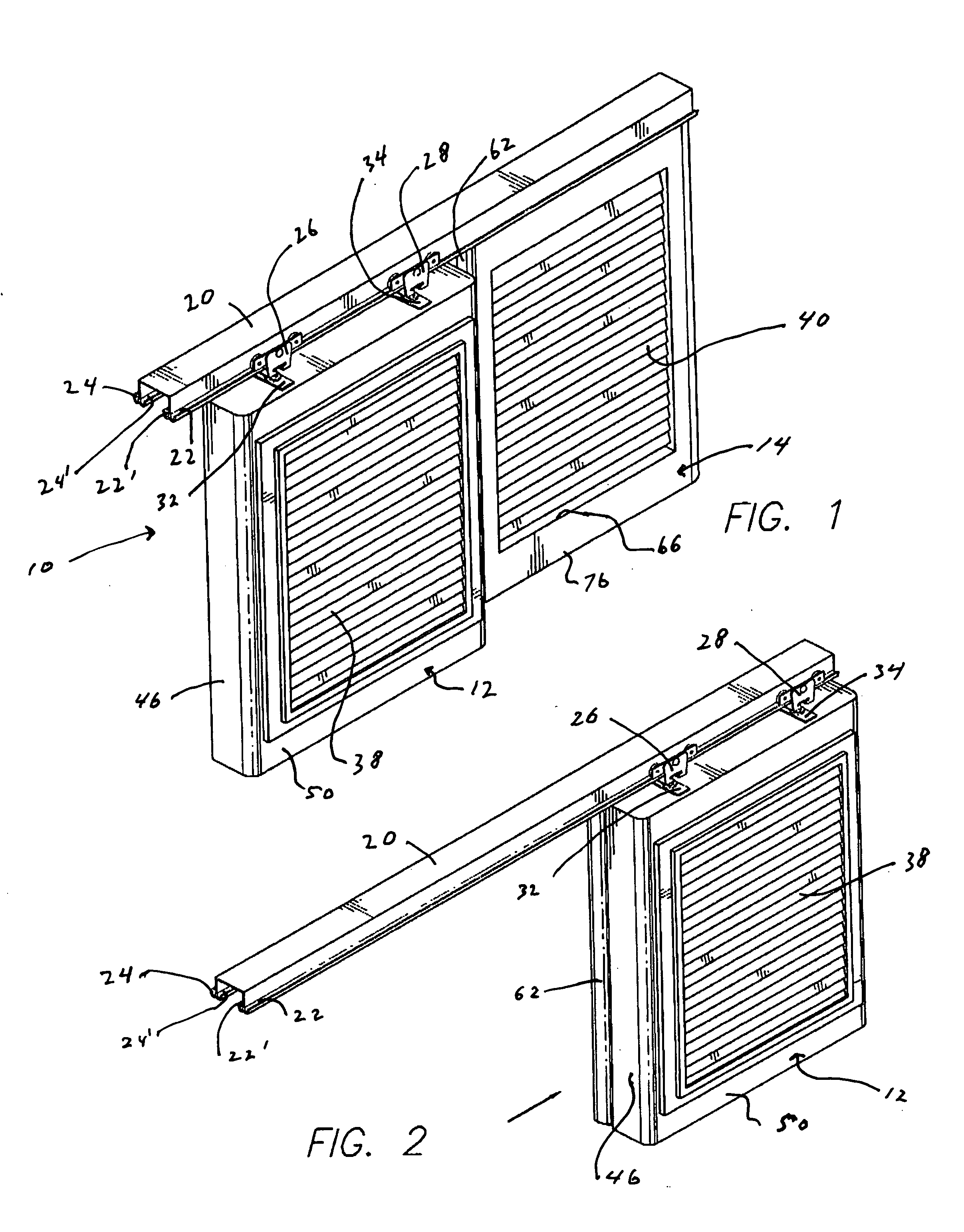
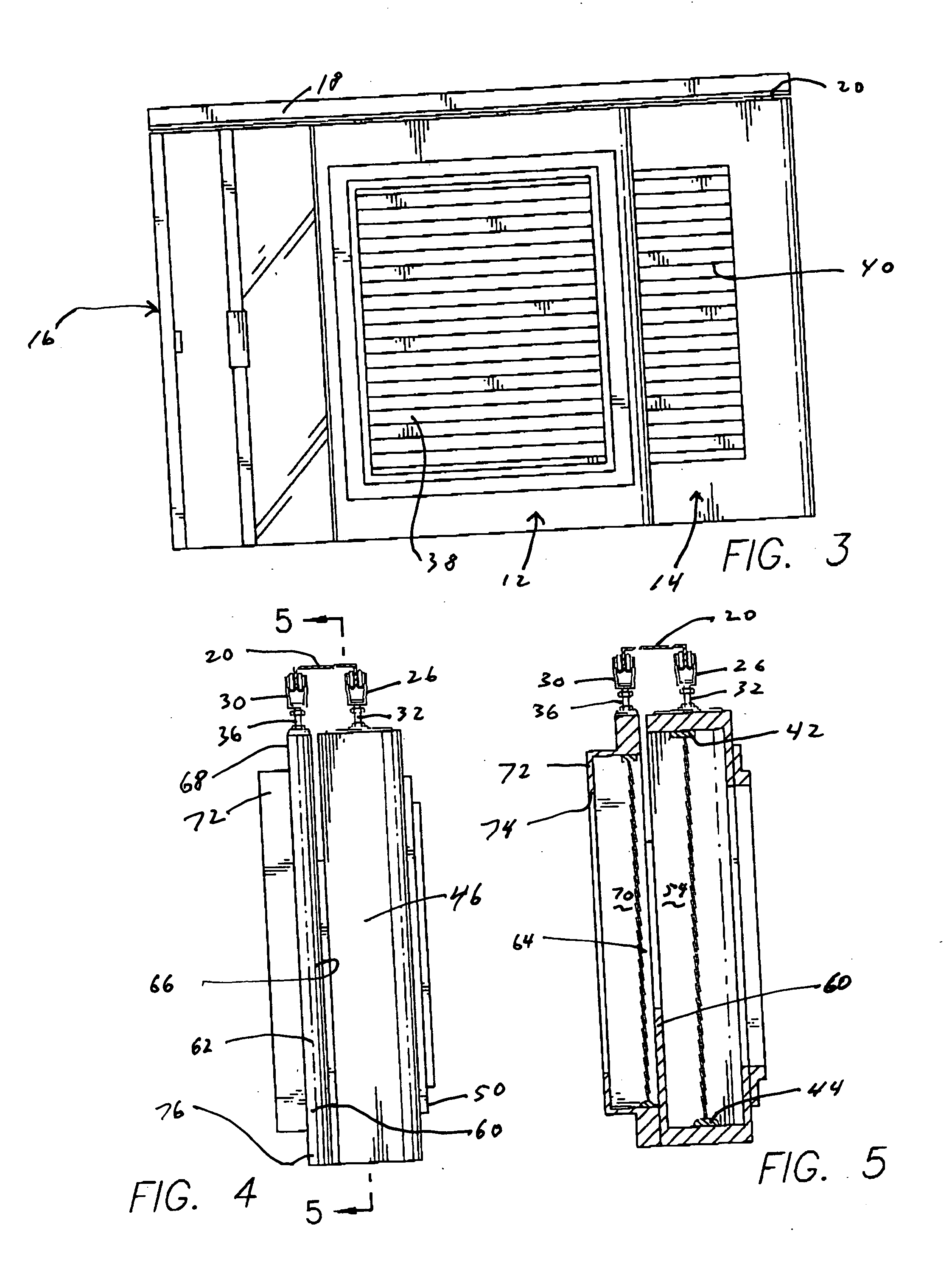
[0013] The invention is shown in FIGS. 1-5, and comprises an assembly 10 of front and rear sashes, respectively 12 and 14, for application adjacent the inside surfaces of a set of sliding glass doors 16 along the top of which extends a header 18 (FIG. 3). For purposes of description of the invention, and as indicated above, reference to “inside surfaces” with respect to the sliding glass doors means adjacent the surface of the sliding glass doors facing into the house or other structure. As seen more clearly in FIGS. 1 and 2, a rail 20 is secured to the underside of the header 18 and formed with opposed upwardly turned flanges defining two sets of opposed front and rear roller tracks, respectively 22, 22′ and 24, 24′. Front roller mechanisms 26 and 28 (FIGS. 1 and 2) are carried on the front tracks 22, 22′. Similarly, and referring to FIGS. 4 and 5, rear roller mechanisms (only one of which, 30, is shown) are carried on the rear tracks 24,24′.

[0014] The front and rear sashes 12 and...


PUM


Abstract

An assembly of sashes containing investitures, such as venetian blinds and / or mesh screens, for application adjacent the inside surfaces of sliding glass doors. In one embodiment, the sashes are suspended from inner and outer tracks of a rail in sliding overlapping relationship. The rail can be secured to the underside of a header disposed along the inside width of the sliding glass doors.

Description

FIELD OF THE INVENTION [0001] The invention relates generally to an assembly of sashes containing investitures such as venetian blinds and / or mesh screens. BACKGROUND OF THE INVENTION [0002] It has long been known to use various investitures, i.e., coverings or adornments, for windows such as various blinds (e.g., venetian blinds) and mesh screens. Blinds have generally been applied the inside of windows, i.e., adjacent the surface of the window facing into the house or other structure, as compared to the use of mesh screens which are generally applied to the outside of windows, i.e., adjacent the surface of the window facing away from the house or other structure. It has of course been known to apply screen doors to the outside of sliding glass doors. U.S. Pat. No. 2,970,642 describes rollingly supporting a screen using suspension bracket to move across the outside header of sliding glass doors. A modern version of sliding glass doors is shown in U.S. Pat. No. 6,497,072. It is also...

Claims


Application Information

Patent Timeline
Patent Type & Authority Applications(United States)
IPC IPC(8): E06B3/46E06B9/26E06B9/52
CPCE06B3/4609E06B9/52E06B9/26
Inventor ORBECK, DAVIDORBECK, MARK
Owner ORBECK DAVID
Why Eureka
Try Eureka