Trigger guard on firearm

a technology for firearms and trigger guards, applied in the field of trigger guards, can solve the problems of unsuitable known trigger guards, unusable inadvertent trigger actuation, and more susceptible to unintended trigger actuation, and achieve the effect of reducing abrasive conta

Inactive Publication Date: 2005-08-25
ROCK RIVER ARMS
View PDF19 Cites 93 Cited by
  • Summary
  • Abstract
  • Description
  • Claims
  • Application Information

AI Technical Summary

Benefits of technology

[0013] The present invention is directed to a firearm having a receiver system that includes a trigger guard of the invention. In an exemplary embodiment, the trigger guard defines a first end and a second end. The first end is configured to mount to a first arm and a second arm extending from the receiver system via a retaining pin. The second end of the trigger guard is configured to mount to a third arm and a fourth arm also extending from the receiver system via a detent. The trigger guard of the invention is configured so that a portion of the first end extends below the first and the second arm so as to minimize abrasive contact between the user's fingers and the first and the second arms.

Problems solved by technology

As can be appreciated, it is undesirable to inadvertently actuate the trigger.
While the trigger guard is used to prevent the inadvertent actuation of the trigger, the known trigger guard is not suitable when the user is wearing gloves, such as during cold weather conditions.
A significant drawback with having the trigger guard in the open position is that the trigger is more susceptible to unintended actuation and therefore unintended firing of the firearm.
Other problems and drawbacks exist with respect to known trigger guards.
For example, certain ergonomic aspects of the pistol grip connection to the lower receiver are not ideal.
Depending on the finish of the arms, the first and second arms can have edges or burrs that can wear and cause abrasions on or even cut the user's finger.
However, with this configuration, the trigger guard cannot be opened, which may be necessary with known trigger guards when a user is wearing thick gloves.
Thus, a firearm using the known trigger guard and using either of the two described methods is less desirable for a user who is operating the firearm in cold weather conditions where gloves are required.

Method used


Image

  • Trigger guard on firearm
  • Trigger guard on firearm
  • Trigger guard on firearm

Examples


Embodiment Construction

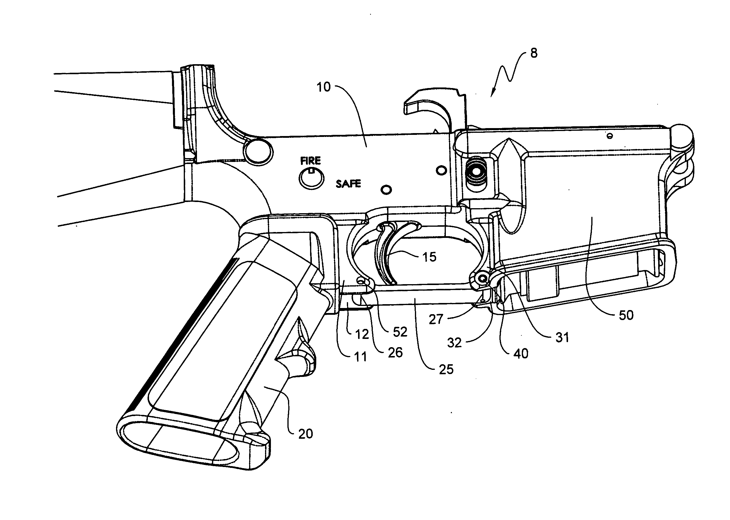
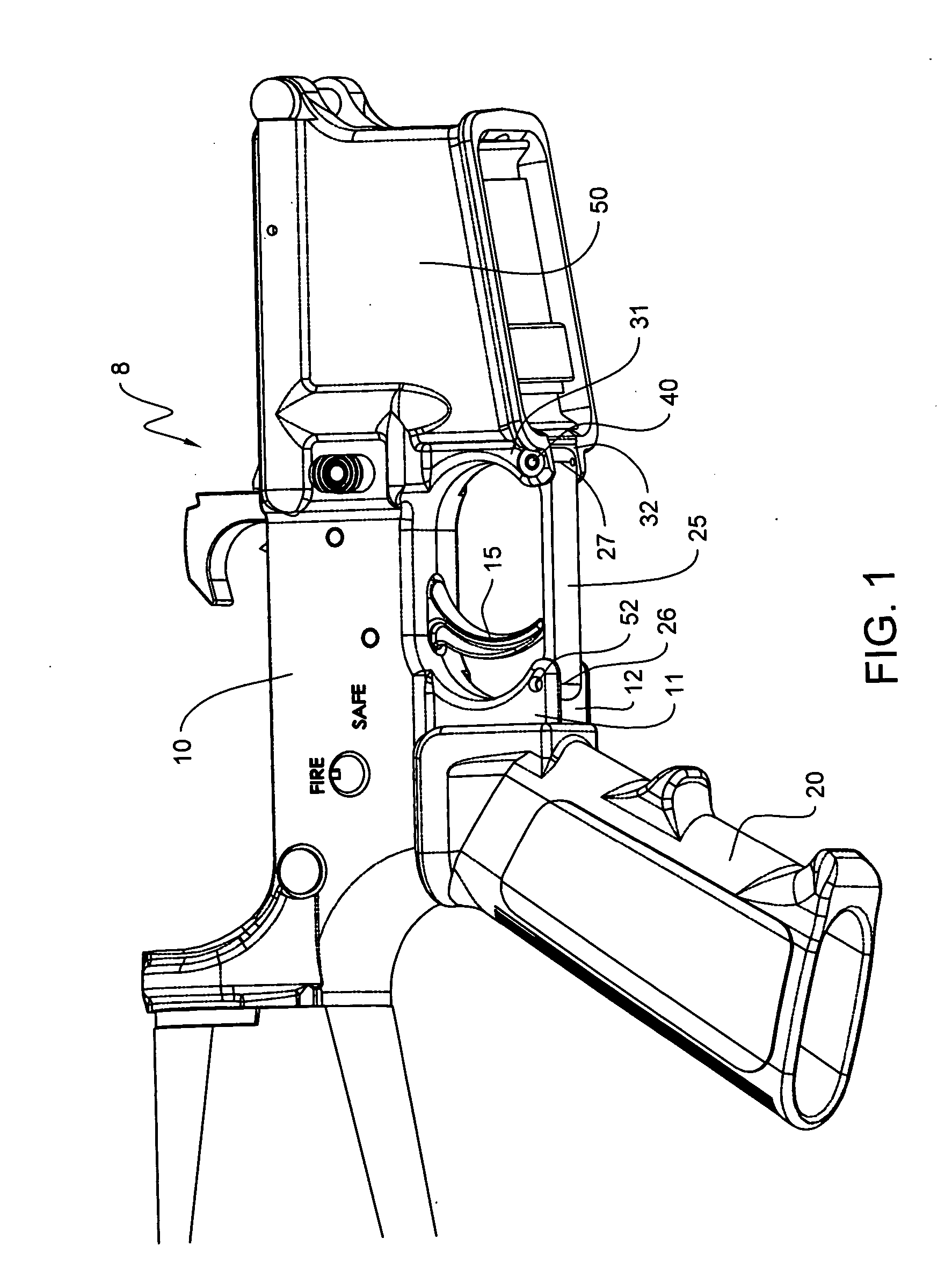
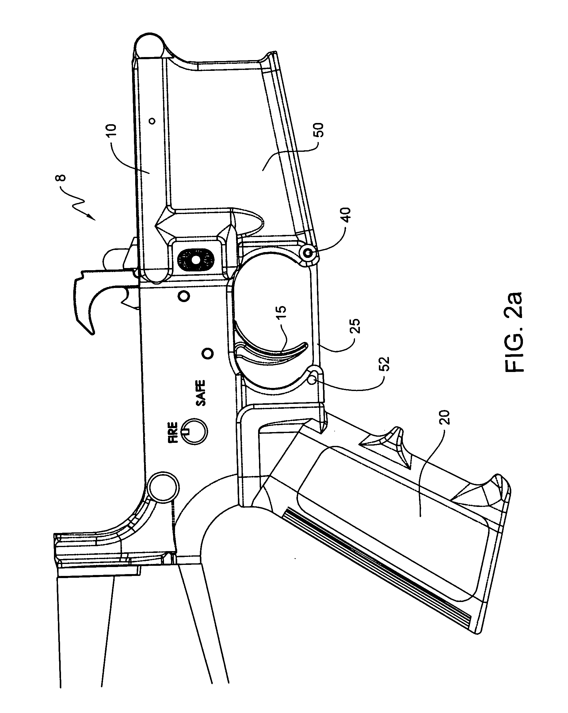
[0026]FIGS. 1-3b depict the prior art trigger guard. FIG. 1 illustrates a partial isometric view of a firearm 8 and depicts how a receiver 10 supports an arm 11 and an arm 12, both of which extend downwardly from the receiver and between a trigger 15 and a grip 20. A trigger guard 25 is shown with a first end 26 rotatably mounted to the arms 11 and 12. A second end 27 is mounted to an arm 31 and an arm 32. The arms 31 and 32 extend downwardly from the receiver 10 and between the magazine well 50 and the trigger 15. The magazine well is the portion of the receiver configured to accept a magazine. The first end 26 of the trigger guard 25 is retained by a pin 52 and the second end 27 is retained by a detent 40. The arms 11, 12, 31, 32 and trigger guard 25 form an enclosure for the trigger 15 to protect the trigger from inadvertent actuation.

[0027] As can be appreciated, the profile of the first arm 11 and second arm 12 are shaped like a partial “C” facing to the right. The profile of ...


PUM


Abstract

A firearm includes a receiver further including a trigger and a trigger guard. The trigger guard comprises a first end and a second end. The first end is configured to mount to a first arm and a second arm of the receiver and is further configured so that a portion of the trigger guard extends below the first and second arm. The second end is configured to mount to a third and forth arm of the receiver. The first end and the second end extend at angles so as to provide additional room for the user's finger in the enclosure surrounding the trigger.

Description

CROSS REFERENCE TO RELATED APPLICATIONS [0001] This application claims benefit to U.S. Provisional Application Ser. No. 60 / 542,905 filed Feb. 9, 2004.BACKGROUND OF THE INVENTION [0002] 1. Field of the Invention [0003] The present invention relates to the field of firearms, more specifically to a trigger guard on a firearm. [0004] 2. Description of Related Art [0005] Referring to FIG. 1, a typical configuration of a receiver system for a firearm is shown and includes a grip 20 that is mounted to a receiver 10. The grip is mounted to the receiver so that the user can hold the grip with a thumb and three fingers while resting a trigger finger on a trigger. [0006] As shown in FIG. 1, the receiver has downwardly extending arms that are used to mount a trigger guard 25 and to form an enclosure for the trigger. Specifically, a first and a second arm 11, 12 extend down between the grip 20 and the trigger 15 and extend below the end of the trigger. A third and fourth arm 31, 32 extend betwee...

Claims


Application Information

Patent Timeline
Patent Type & Authority Applications(United States)
IPC IPC(8): F41A19/11
CPCF41A19/11
Inventor FINN, JAMES
Owner ROCK RIVER ARMS
Why Eureka
Try Eureka