Energized PTFE seal for butterfly valve

a technology of energized ptfe and butterfly valve, which is applied in the field of valves, can solve problems such as affecting the duty cycle of the overall process equipment, and achieve the effects of reducing wear, reducing seal wear, and reducing wear

Inactive Publication Date: 2018-09-20
NOR CAL PRODS
View PDF2 Cites 10 Cited by
  • Summary
  • Abstract
  • Description
  • Claims
  • Application Information

AI Technical Summary

Benefits of technology

[0012]The valve body wall against which the seal abuts when closed defines a seat and is also formed with a particular geometry including a contour where contact occurs with the J-LOCK seal's semi-circular section outer surface. Thus, two surfaces come into contact with each other, limiting this contact to a small area to minimize seal wear by PTFE seal material (or other seal material) coming into contact with the valve body wall which is typically formed of metal, for a shorter percentage of each stroke of the valve. The rounded shape of the seal at the semi-circular section, coupled with the offset shaft in the body (discussed below) ensures that the seal pulls away from the body wall quickly. This reduces wear of the seal. The seal surface in the valve body wall provides a gradual compression to the seal and reduces wear.
[0013]A hub upon which the valve element rotates is preferably offset from a centerline of the throttle plate. Thus, the perimeter of the seal follows a somewhat unique path which beneficially causes the seal to quickly come into contact with seating portions of the adjacent valve body wall in a manner which minimizes abrasive contact, but rather facilitates resting of the wall of the seal to come against a side wall in a manner that minimizes abrasiveness.
[0014]Accordingly, a primary object of the present invention is to provide a valve which can provide a robust seal to maintain a high vacuum environment on an upstream side of the seal.
[0015]Another object of the present invention is to provide a throttling butterfly vacuum valve which has a perimeter seal which minimizes abrasive contact when closing and maintains a secure seal at the perimeter.
[0016]Another object of the present invention is to provide a valve which maintains a high quality seal both under low vacuum and low pressure differential conditions, as well as when a pressure differential similar to atmospheric pressure is encountered.
[0017]Another object of the present invention is to provide a throttling butterfly valve for high vacuum gas handling which provides precise control for maintenance of desired pressure, especially within a test chamber upstream of the valve.

Problems solved by technology

Any leakage around a perimeter of such a seal can have a significant impact on such “pump down” times, and undesirably affect duty cycle for the overall process equipment.

Method used


Image

  • Energized PTFE seal for butterfly valve
  • Energized PTFE seal for butterfly valve
  • Energized PTFE seal for butterfly valve

Examples


Embodiment Construction

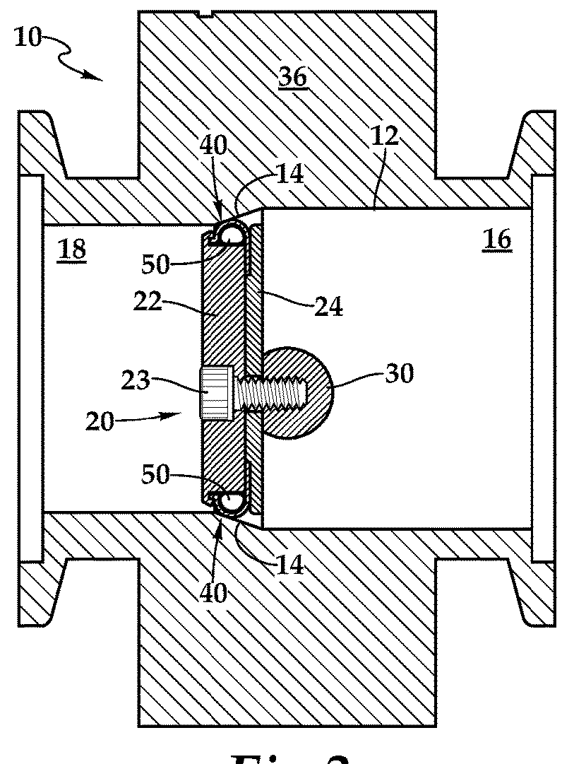
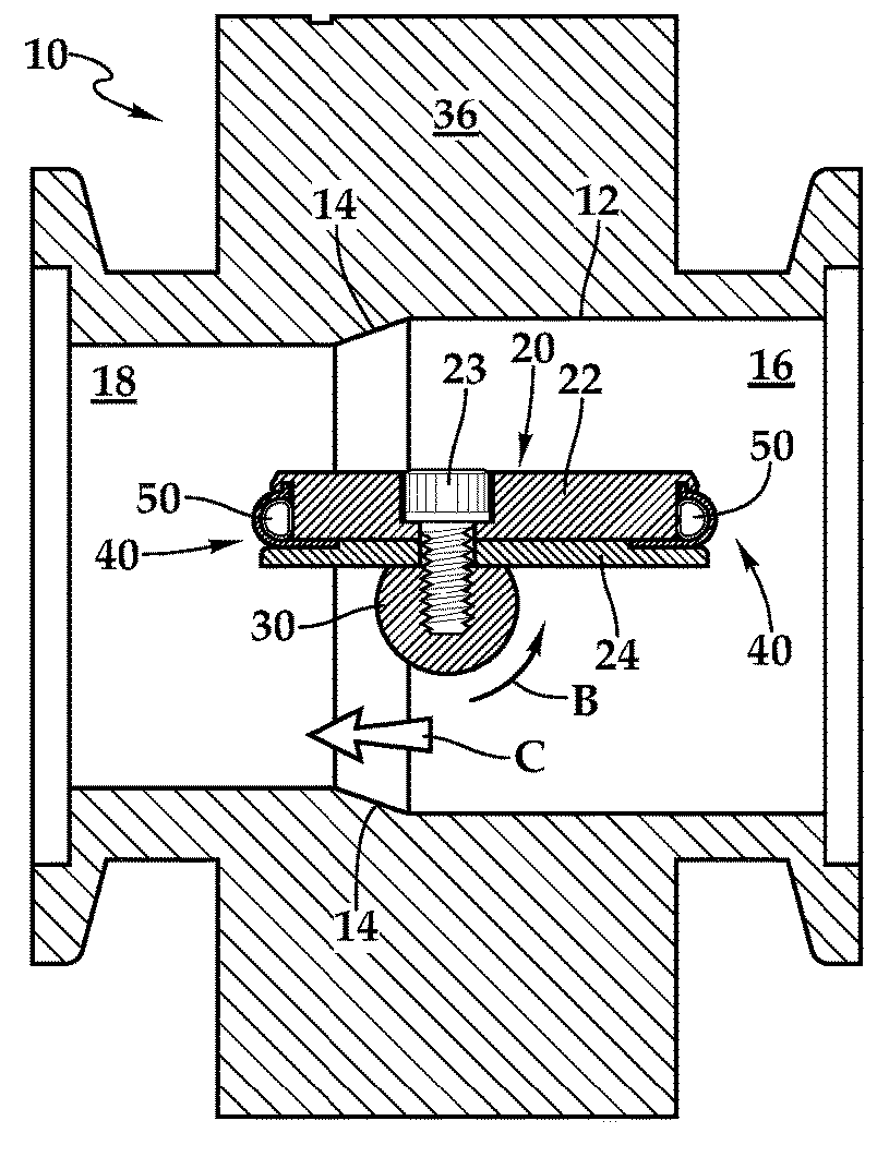
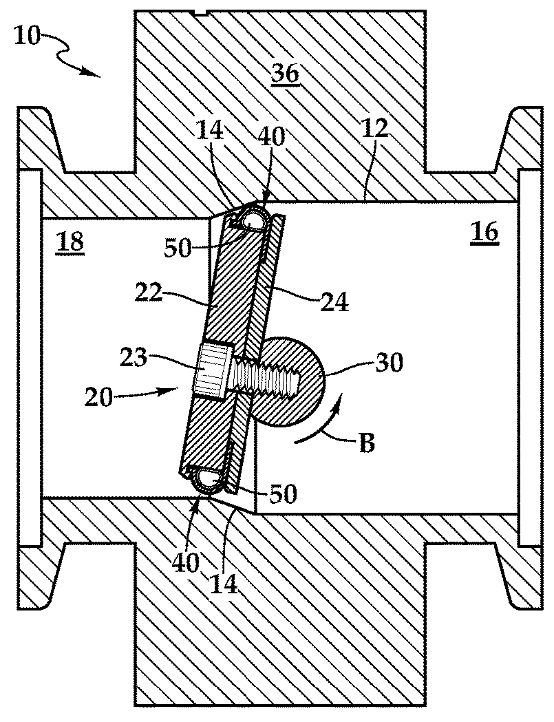
[0029]Referring to the drawings, wherein like reference numerals represent like parts throughout the various drawing figures, reference numeral 10 is directed to a valve (FIG. 8), particularly configured for use in handling high vacuum, such as upstream of a vacuum pump 120 and downstream of a high vacuum region, such as a vacuum process chamber 110 within a vacuum handling system 100. The valve 10 is configured with an offset shaft 30 orientation and with an energized perimeter seal 40 to provide a high quality seal and minimize disruption of the vacuum environment adjacent thereto.

[0030]In essence, and with particular reference to FIGS. 1-3, 6 and 7, basic details of the valve 10 are described, according to a preferred embodiment. The valve 10 fits within a housing 36 having a bore 16, 18 passing therethrough. The valve 10 includes a throttle plate 20 which is pivotably attached within the housing 36 to selectively open and close passage through the bore 16, 18. The throttle plate...


PUM


Abstract

A plate within the valve pivots about a shaft to cause the plate to transition between an open position and a closed position within a bore passing through the housing of the valve. The plate has a perimeter seal thereon which abuts against a tapering seat of the bore when the throttle plate is in a closed orientation. The seal has a curving form over a recess and an energy source, such as the toroidal spring in the recess, to energize the seal and allow it to maintain secure contact against the seat. The shaft is offset from the centerline of the bore and the plate is mounted to the shaft at a location offset from the center point of the plate, so that rotation of the plate causes the plate to swing somewhat into a closed position, minimizing abrasive contact between the seat and seal during closing.

Description

CROSS-REFERENCE TO RELATED APPLICATIONS[0001]This application claims benefit under Title 35, United States Code § 119(e) of U.S. Provisional Application No. 62 / 471,137 filed on Mar. 14, 2017.FIELD OF THE INVENTION[0002]The following invention relates to valves generally in the form of butterfly valves which include seals at a perimeter thereof which seal to a surrounding wall. More particularly, this invention relates to valves, such as throttling butterfly valves, particularly for use in vacuum handling equipment, which include energized seals for robust sealing at various different gas pressure differentials across the valve, and which feature a pivot shaft offset from a center of a valve plate and offset from a centerline of a bore in which the valve plate is located.BACKGROUND OF THE INVENTION[0003]Vacuum handling equipment, including chambers, conduits, valves and pumps, as well as related equipment, are used in a variety of industries including certain specialized forms of man...

Claims


Application Information

Patent Timeline
Patent Type & Authority Applications(United States)
IPC IPC(8): F16K1/226F02D9/10
CPCF16K1/2268F02D9/108F02D9/1015F16K1/2263F16K1/2261
Inventor HADLEY, JEFFCASAROTTI, SEAN
Owner NOR CAL PRODS
Why Eureka
Try Eureka