French door cooking appliance closure system

a technology for cooking appliances and doors, applied in the field of french door cooking appliance closure systems, can solve the problems of not being completely satisfactory for every application, affecting the traffic pattern of the kitchen or the access of the door, and the oven cavity could be contaminated, so as to minimize the abrasion of the first gasket, minimize wear, and minimize the effect of potential wear

Inactive Publication Date: 2007-10-25
MAYTAG
View PDF48 Cites 17 Cited by
  • Summary
  • Abstract
  • Description
  • Claims
  • Application Information

AI Technical Summary

Benefits of technology

[0013]The first and second control arms are operatively connected to a support bracket through a linkage control arm. The linkage control arm establishes the arcuate path tracked by first and second ends of the door control arms, as well as a particular timing of the doors. With this arrangement, as the doors transition between the open and closed positions, the linkage control arm engages the cam follower. The cam follower travels along the camming surface to provide for a smooth transition.
[0014]Each of the doors has an associated gasket for use in sealing the oven cavity when the doors are closed. In accordance with the invention, one of the doors is provided with an annular gasket, while the other door essentially incorporates a less that fully annular, preferably 3-sided, gasket. Most preferably, a three-quarter gasket is employed. With this arrangement, each of the gaskets has three sides adapted to seal against the cabinet shell, while the fourth side of the first gasket is adapted to seal against an extension provided on the other door. An important aspect of the invention is to minimize abrasion on the first gasket by designing both the gasket contact point or line, and the door timing so as to produce a contact arrangement similar to that exhibited with standard single door units.
[0015]In connection with the invention, the gasket configurations and constructions, along with the construction and operation of the door linkage system, combine to provide a synergistic effect in minimizing potential wearing of the

Problems solved by technology

While this type of oven door has found wide spread use, it is not entirely satisfactory for every application.
Otherwise, the opened door could interfere with traffic patterns in the kitchen or with access to other cabinetry.
In addition, such an oven door may require a consumer to stand at a side of the appliance to fully access the oven cavity.
In particular, if the timing is off, undue seal wear can occur, resulting in undesira

Method used


Image

  • French door cooking appliance closure system
  • French door cooking appliance closure system
  • French door cooking appliance closure system

Examples


Embodiment Construction

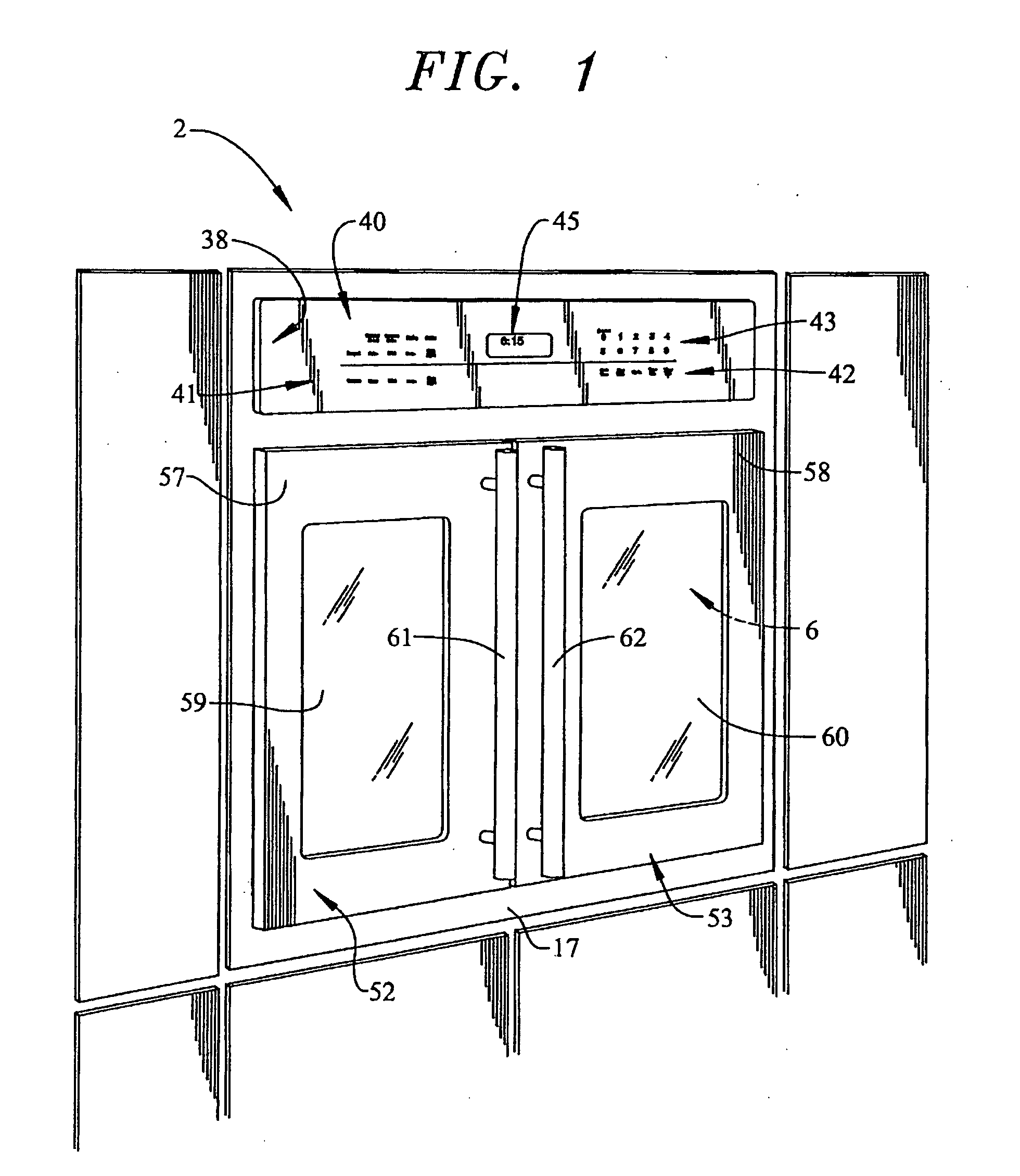
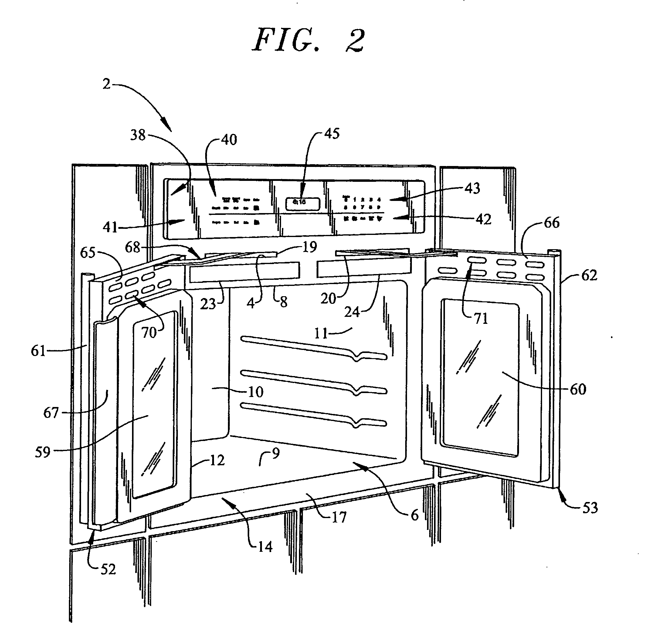
[0033]With initial reference to FIGS. 1 and 2, a cooking appliance constructed in accordance with the present invention is generally indicated at 2. As depicted, cooking appliance 2 constitutes a wall oven. However, it should be understood that the present invention is not limited to this particular model type and can be incorporated into various types of oven configurations, e.g., cabinet mounted ovens, as well as both slide-in and free-standing ranges. In any event, in the embodiment shown, cooking appliance 2 constitutes a single wall oven unit including a frame 4 (best seen in FIG. 3) that supports, at least in part, an oven cavity 6. Oven cavity 6 includes a top wall 8, a bottom wall 9, a rear wall 10 and opposing side walls 11 and 12 that collectively define a frontal opening 14. In a manner known in the art, frontal opening 14 is surrounded by a face frame portion 17 which provides an overall aesthetic finish to cooking appliance 2. Preferably, face frame portion 17 is provid...


PUM


Abstract

A cooking appliance includes an oven cavity accessed through first and second French-style doors that are connected to the appliance through a door linkage system. The door linkage system establishes a particular timing of door openings and closings to minimize potential wear of a door gasket. That is, each of the doors has an associated gasket for use in sealing the oven cavity when the doors are closed. One of the doors is provided with an annular gasket, while the other door essentially incorporates a less that fully annular, preferably 3-sided or a three-quarter gasket. With this arrangement, each of the gaskets has three sides adapted to seal against a cabinet shell portion of the appliance, while the fourth side of the first gasket is adapted to seal against an extension provided on the other door.

Description

CROSS-REFERENCE TO RELATED APPLICATION[0001]The present application claims the benefit of U.S. Provisional Patent Application Ser. No. 60 / 793,251 filed Apr. 26, 2006 entitled “French Door Cooking Appliance Closure System.”BACKGROUND OF THE INVENTION[0002]1. Field of the Invention[0003]The present invention pertains to the art of cooking appliances and, more particularly, to a door linkage system for an oven having French-style doors. Even more specifically, the invention is directed to a French-style door seal mounting and timing arrangement designed to minimize seal gasket wear.[0004]2. Discussion of the Prior Art[0005]It is widely known to provide a cooking appliance, such as an oven range or a wall oven, with a single, generally rectangularly shaped door that pivots about a horizontal axis. That is, a top portion of the oven door is pulled outward from the appliance about horizontally disposed hinges and lowered into a horizontal position to provide access to the oven cavity. Whi...

Claims


Application Information

Patent Timeline
IPC IPC(8): F24C15/04
CPCF24C15/023F24C15/021
Inventor LARSEN, CHRISTOPHER A.LEVI, DAVID E.PICKERING, MARK A.
Owner MAYTAG
Why Eureka
Try Eureka