
Bicycle derailleur

a derailleur and bicycle technology, applied in the direction of cycle equipment, gearing, riding equipment, etc., can solve the problems of reducing riding/shifting performance, and achieve the effect of reducing potential jams

Inactive Publication Date: 2005-09-01
SHIMANO SINGAPORE PRIVATE LTD
View PDF4 Cites 28 Cited by
  • Summary
  • Abstract
  • Description
  • Claims
  • Application Information

AI Technical Summary

Benefits of technology

[0009] One object of the present invention is to provide a bicycle derailleur, which reduces potential jams when objects contact the derailleur to push the chain guide of the derailleur into the wheel.
[0010] Another object of the present invention is to provide a bicycle derailleur that smoothly and reliably shifts the chain over the various sprockets.
[0011] Another object of the present invention is to provide a bicycle derailleur that is relatively simple and inexpensive to manufacture and assemble.
[0012] Still another object of the present invention is to provide a bicycle derailleur that is strong, yet relatively lightweight.

Problems solved by technology

Such contact can jam the rear wheel and / or the rear derailleur, resulting in decreased riding / shifting performance.

Method used


Image

  • Bicycle derailleur
  • Bicycle derailleur
  • Bicycle derailleur

Examples


second embodiment

[0060] Referring now to FIGS. 15 and 16, a modified tension pulley 256 is illustrated in accordance with a second embodiment of the present invention. The tension pulley 256 is designed to be used in the chain guide 36 of the first embodiment in place of the tension pulley 56 of the first embodiment. The tension pulley 256 of this second embodiment is identical to the tension pulley 56 of the first embodiment, except the tension pulley 256 includes a recess 280 disposed about a rotation axis 2X to form a modified projection 282 in place of the projection 82 of the first embodiment. Thus, the tension pulley 256 will not be discussed and / or illustrated in detail herein. Rather, it will be apparent to those skilled in the art from this disclosure that the descriptions and illustrations of the tension pulley 56 of the first embodiment also apply to the tension pulley 256 of this second embodiment, except as explained and illustrated herein.

[0061] The recess 280 is identical to the rece...


PUM


Abstract

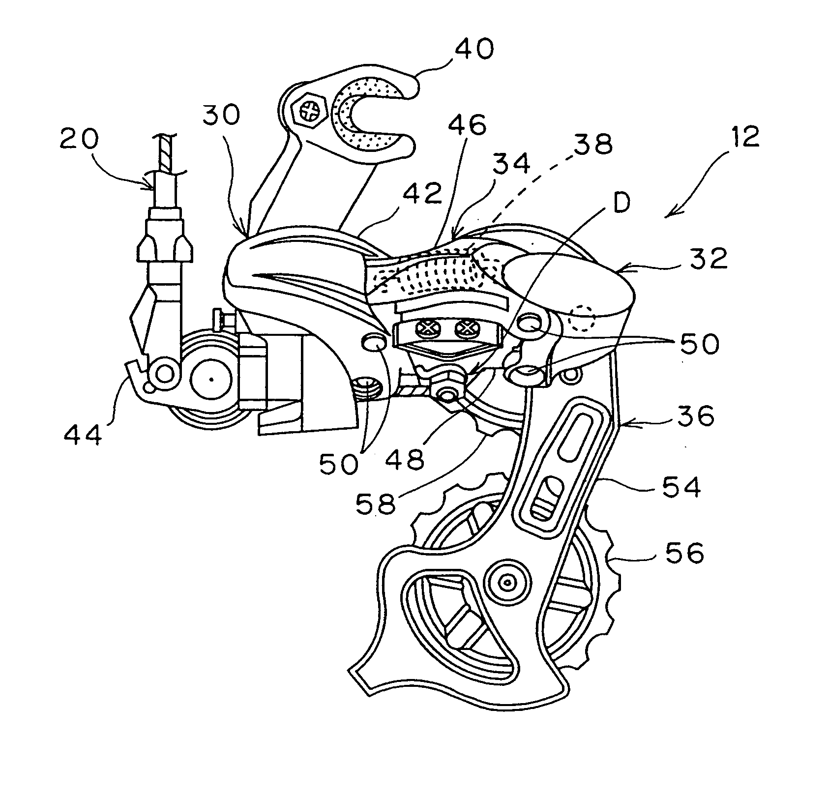
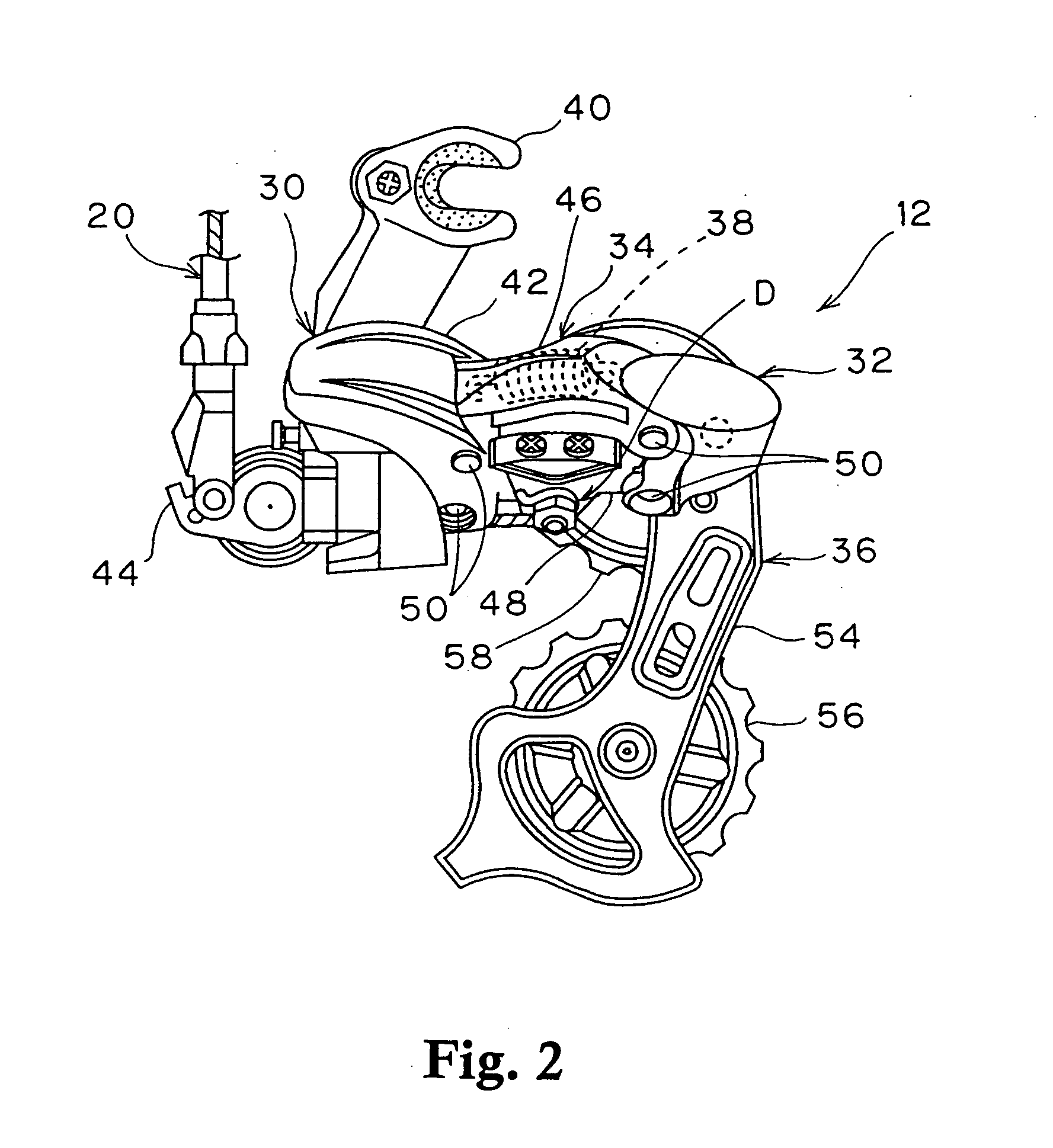
A bicycle derailleur is provided with a chain guide that basically includes inner and outer guide plates, a guide pulley and a tension pulley. The tension pulley is rotatable about a rotation axis between free ends of the guide plates. The tension pulley has an annular recess disposed about the rotation axis to form a projection. The inner guide plate has a guide section with a radially outermost edge. Preferably, the outermost edge of the guide section is located in the annular recess, and the projection projects axially further from a center plane of the tension pulley than the outermost edge. Preferably, the chain guide includes a dust cap coupled between the inner guide plate and the tension pulley. Preferably, the outermost edge of the guide section is located radially inwardly of the projection and radially outwardly of the annular portion of the dust cap.

Description

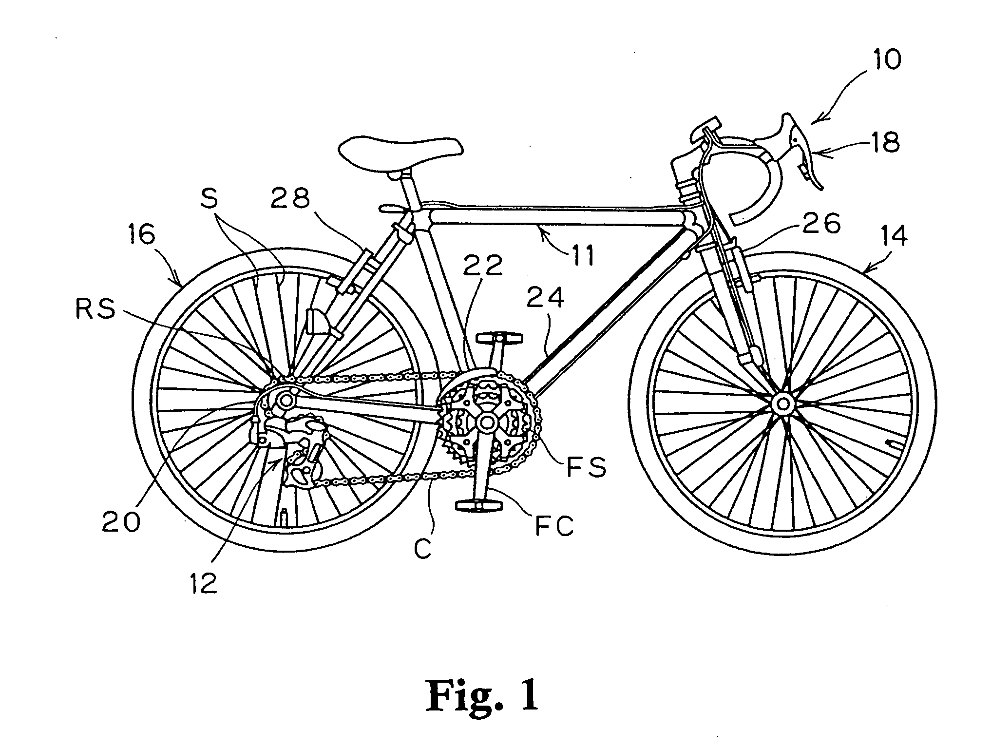
BACKGROUND OF THE INVENTION [0001] 1. Field of the Invention [0002] This invention generally relates to a bicycle derailleur. More specifically, the present invention relates to a rear bicycle derailleur having an inner plate and tension pulley configured to prevent jamming of the derailleur when pushed into a moving bicycle wheel. [0003] 2. Background Information [0004] Bicycling is becoming an increasingly more popular form of recreation as well as a means of transportation. Moreover, bicycling has become a very popular competitive sport for both amateurs and professionals. Whether the bicycle is used for recreation, transportation or competition, the bicycle industry is constantly improving the various components of the bicycle. One component that has been extensively redesigned is the bicycle derailleur. [0005] Typically, a bicycle derailleur has a base member and a chain guide movably coupled to the base member via a linkage assembly. The base member is coupled to the frame of ...

Claims


Application Information

Patent Timeline
Patent Type & Authority Applications(United States)
IPC IPC(8): B62M9/126
CPCB62M9/126
Inventor SZE, RAYMOND TAN BOONHOE, JIMMY SUA GIN
Owner SHIMANO SINGAPORE PRIVATE LTD
Learn More