Thermoplastic nylon adhesive matrix having a uniform thickness and composite laminates formed therefrom
a technology of thermoplastic nylon and adhesive web, which is applied in the direction of weaving, synthetic resin layered products, coatings, etc., can solve the problem that the type of adhesive web is usually not easy to manufactur
- Summary
- Abstract
- Description
- Claims
- Application Information
AI Technical Summary
Benefits of technology
Problems solved by technology
Method used
Image
Examples
example 1
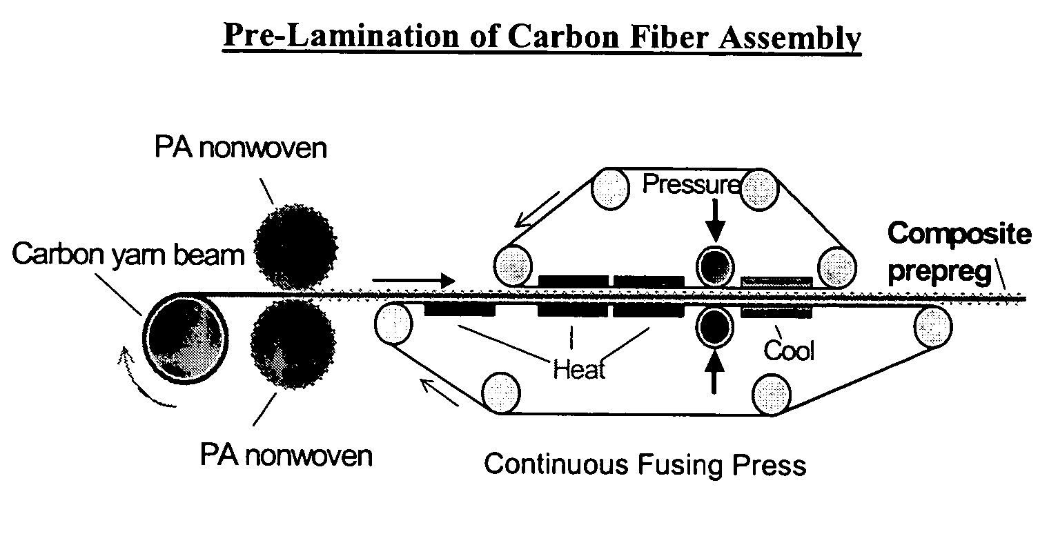
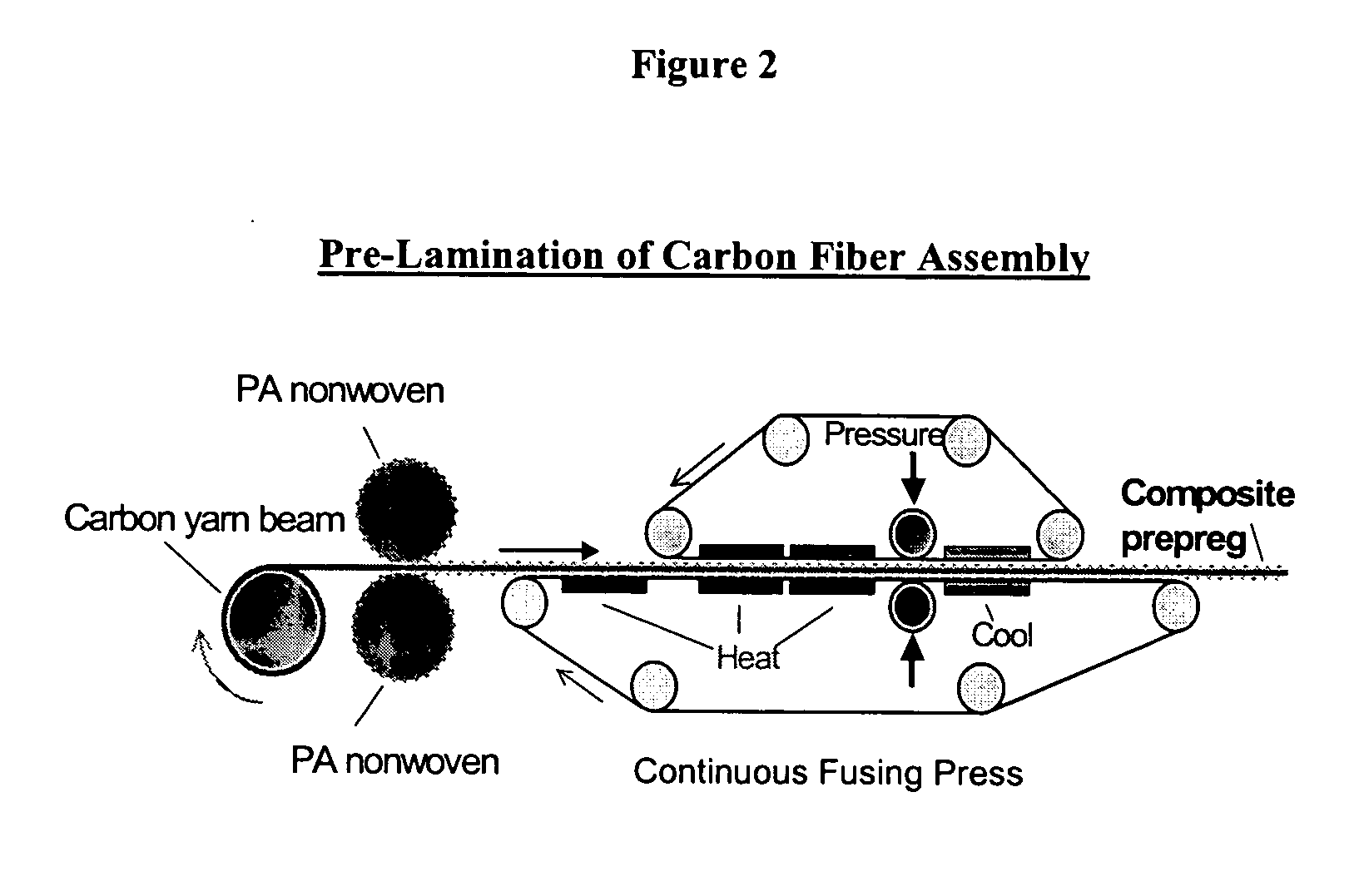
Pre-Lamination of Uniaxial Carbon Fiber Assembly Using Nylon 12 Based Self-Bonded Fabric
[0039]FIG. 2 is an illustration of the pre-lamination process. Reinforcing carbon fibers are supplied from a beam, separated by a comb to distribute the filaments evenly across the width of 16 inches into a tape-assembly of loose fibers. The yarn contains 700 filaments at 10 denier per filament (15-20 yarns per inch). The tape is pulled, at a line speed of about 20 feet per minute by the conveyor belt of the bonder and onto a winder. Prior to entering the bonder, which is at a temperature of 310° F., the carbon fiber assembly is contacted by a polymeric.
[0040] In a second operation, cut sections of the pre-laminated composite are layered so that the reinforcing carbon fibers are aligned at controlled angles to each other to form the desired lay-up. These layer lay-ups are placed into a molding envelope having a contoured surface and a flexible membrane encasing the lay-up. Fittings are provided...
example 2
Laminate Production with Nylon 12 Polymer Blend Web RFE-Polymeric Adhesive Web Production
[0041]
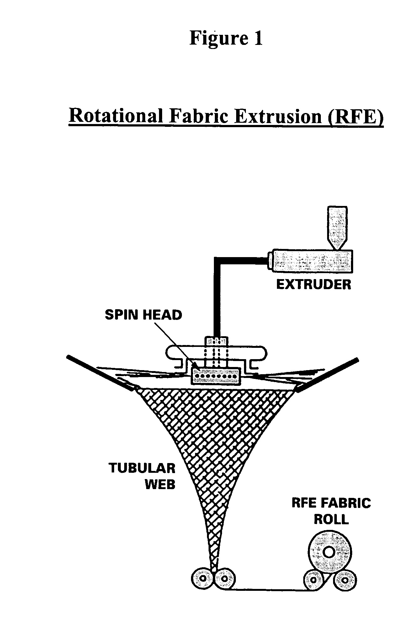
Raw Material:Nylon 1290 parts (-NH3 terminated)Nylon Terpolymer10 partsType:(Nylon 12, Nylon 6-6, Nylon 6)Composition:50 / 25 / 25 - parts by weightMixing:Raw materials are dry-blended in aTilted Drum Blender for 20 minutes.Extrusion System:Rotational Fabric Extrusion, Shown inWinder:Standard textile winderExtruder:2½ -inch standard single-screw extruderDie Type:Radial, 16 spinneretsQuench:Radial (ambient air), to accommodate thedieNip Roll:Pneumatic nip rollWinder:Standard textile winder
[0042] The freshly mixed blend of raw material is fed into the hopper of a six temperature zone extruder, which is set at a temperature profile to melt the polymer to a melt temperature of about 500° F. Filaments are extruded from the extruder through a rotating die revolving at 500 to 3000 rotations per minute, with simultaneous air quenching, to form a self-bonded nonwoven web having a substantial fiber ali...
example 3
Laminate Production with Unblended Nylon 12
[0044] The procedure of Example 2 is repeated except that the polymeric adhesive web consists of pure amine-modified Nylon 12.
PUM
| Property | Measurement | Unit |
|---|---|---|
| Percent by mass | aaaaa | aaaaa |
| Thickness | aaaaa | aaaaa |
| Adhesivity | aaaaa | aaaaa |
Abstract
Description
Claims
Application Information
 - R&D
- Intellectual Property
- Life Sciences
- Materials
- Tech Scout
- Unparalleled Data Quality
- Higher Quality Content
- 60% Fewer Hallucinations
Browse by: Latest US Patents, China's latest patents, Technical Efficacy Thesaurus, Application Domain, Technology Topic, Popular Technical Reports.
© 2025 PatSnap. All rights reserved.Legal|Privacy policy|Modern Slavery Act Transparency Statement|Sitemap|About US| Contact US: help@patsnap.com


