Method and apparatus for determining protection transmission unit allocation

a transmission unit and allocation method technology, applied in the field of communication networks, can solve the problems of inability to allocate time slots to channels, inability to pass flow onto the ring, and stranded bandwidth on particular spans,

Active Publication Date: 2005-09-08
CIENA
View PDF6 Cites 8 Cited by
  • Summary
  • Abstract
  • Description
  • Claims
  • Application Information

AI Technical Summary

Benefits of technology

[0014] As described in greater detail below, protection transmission unit allocation may be determined by disseminating connection information, connection identification information, and a prioritization scheme, to nodes on the network and allowing them to deterministically allocate protection transmission units to flows on the network. In this way, network elements forming physical or logical rings may ascertain the location on protection for a given flow without the communication of maps from a central controller. By enabling each network element to make an independent determination, it is possible for each network element to determine the location of traffic of particular interest without requiring communication of the location information from a central control module. By providing each network element with connection information for flows being handled by the ring and a priority mechanism, it is possible to allow each element to make a determination and, since each is starting with the same information and running the same priority determination, each will end up with the same result. Aspects of the invention may be employed for example in a SONET / SDH based network, a mesh network, or other type of network with dedicated protection paths and transmission allocation on those protection paths.

Problems solved by technology

Maintaining traffic on the same time slot on all spans in the ring provided an easy way to locate the traffic on the protection path in the even of a failure, but proved to be inefficient in that bandwidth may be stranded on particular spans and unable to be allocated to a particular flow if that same time slot weren't available all the way through the ring.
Similarly, the requirement that STS#s be placed on contiguous time slots resulted in time slots not being allocated to a channel despite the fact that there was sufficient bandwidth, in the aggregate, to handle the channel on the ring.
For example, if a channel needed 3 STS#s and there were two sets of 2 contiguous STS#s, the flow would not be able to be passed onto the ring despite the fact that there was sufficient capacity on the ring to handle the new channel.
This becomes more complicated in mesh-topology networks in which multiple paths may be used to back up flows through a given node.
Unfortunately, every time a new connection was added or a connection was deleted, these maps needed to be changed.
Additionally, the deployed base of SONET / SDH networks did not have a convenient centralized computing platform, which complicated deployment into existing networks.
Finally, when multiple failure scenarios were to be taken into account, the number of maps required to be generated and maintained grew to be quite large.

Method used


Image

  • Method and apparatus for determining protection transmission unit allocation
  • Method and apparatus for determining protection transmission unit allocation
  • Method and apparatus for determining protection transmission unit allocation

Examples


Embodiment Construction

[0028] The following detailed description sets forth numerous specific details to provide a thorough understanding of the invention. However, those skilled in the art will appreciate that the invention may be practiced without these specific details. In other instances, well-known methods, procedures, components, protocols, algorithms, and circuits have not been described in detail so as not to obscure the invention.

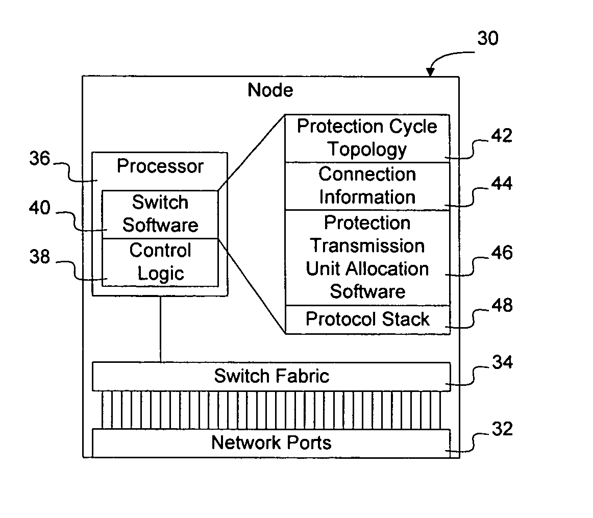
[0029] As described in greater detail below, protection transmission unit allocation may be determined by disseminating connection information, connection identification information, and a prioritization scheme, to nodes on the network and allowing them to deterministically allocate protection transmission units to connections on the network. In this way, network elements forming physical or logical rings may ascertain the location on protection for a given connection without requiring maps to be distributed by a central controller. By enabling each network element to m...


PUM


Abstract

Protection transmission unit allocation, such as STS# in a SONET/SDH network utilizing time slot interchange on the working path, may be determined by disseminating connection information, connection identification information, and a prioritization scheme, to nodes on the network and allowing them to deterministically allocate protection transmission units to connections on the protection cycle. Network elements forming physical or logical rings may thus ascertain the location on protection for a given connection without requiring protection unit allocation to be disseminated from a central controller. Since each node is starting with the same connection information and running the same priority determination, each will end up with the same result and will know where to place and find connections on protection. Aspects of the invention may be employed for example in a SONET/SDH based network, a mesh network, or other type of network with dedicated protection paths and transmission allocation on those protection paths.

Description

BACKGROUND [0001] 1. Field [0002] This application relates to communication networks and, more particularly, to a method and apparatus for determining protection transmission unit allocation. [0003] 2. Description of the Related Art [0004] Data communication networks may include various computers, servers, hubs, switches, nodes, routers, proxies, and other devices coupled to and configured to pass data to one another. These devices will be referred to herein as “network elements.” Data is communicated through the data communication network by passing protocol data units, such as frames, packets, cells or segments, between the network elements by utilizing one or more communication links. A particular protocol data unit may be handled by multiple network elements and cross multiple communication links as it travels between its source and its destination over the network. [0005] The various network elements on the communication network communicate with each other using predefined sets...

Claims


Application Information

Patent Timeline
Patent Type & Authority Applications(United States)
IPC IPC(8): G06F12/14
CPCH04J3/14H04J3/085
Inventor BENVENUTI, NICOLASTEELE, DAVID
Owner CIENA
Why Eureka
Try Eureka