Hybrid clean-energy power-supply framework

a power-supply framework and hybrid technology, applied in the direction of machines/engines, reciprocating combination engines, secondary cells servicing/maintenance, etc., can solve the problems of not being designed well, still poorly investigated, and the above-described conventional technique still has many drawbacks, so as to reduce the cost of power generation, prevent the effect of island effect, and improve photoconductivity

Active Publication Date: 2005-09-15
YUAN ZE UNIV
View PDF5 Cites 76 Cited by
  • Summary
  • Abstract
  • Description
  • Claims
  • Application Information

AI Technical Summary

Benefits of technology

[0012] The object of the present invention is to provide a hybrid clean-energy power-supply framework, using a central processing unit to monitor and dispatch each of the power generating and supply systems, calculating accurately the system capacity, determining an optimal generation model, ensuring the reliability of power-supply and reducing the cost of power generation.
[0013] The other object of the present invention is to provide a mechanism for a selectively grid-connected or stand-alone power-supply system that is capable of preventing island effect. When the utility power is normal the grid-connected with utility power is selected and once the utility power is interrupted, isolating the utility power and dispatching load, the power-supply of partial loop is continued.
[0014] The hybrid clean-energy power-supply framework that can achieve the above-mentioned objects of the present invention is a hybrid clean-energy power-supply framework that integrates a fuel cell, photovoltaic, and wind-power energy. The fuel cell, applying the electrochemical reaction principle, using hydrogen and oxygen as reactants, produces merely pure water, direct current, and waste heat; all such three products are us

Problems solved by technology

At present, a device of feeding a single system into a utility power has been developed, but it is not considered a mechanism for feeding those three systems into the utility power together.
Moreover, a function, which is designed in the sense of the cost oriented and economical dispatching rule for control

Method used


Image

  • Hybrid clean-energy power-supply framework
  • Hybrid clean-energy power-supply framework
  • Hybrid clean-energy power-supply framework

Examples


Embodiment Construction

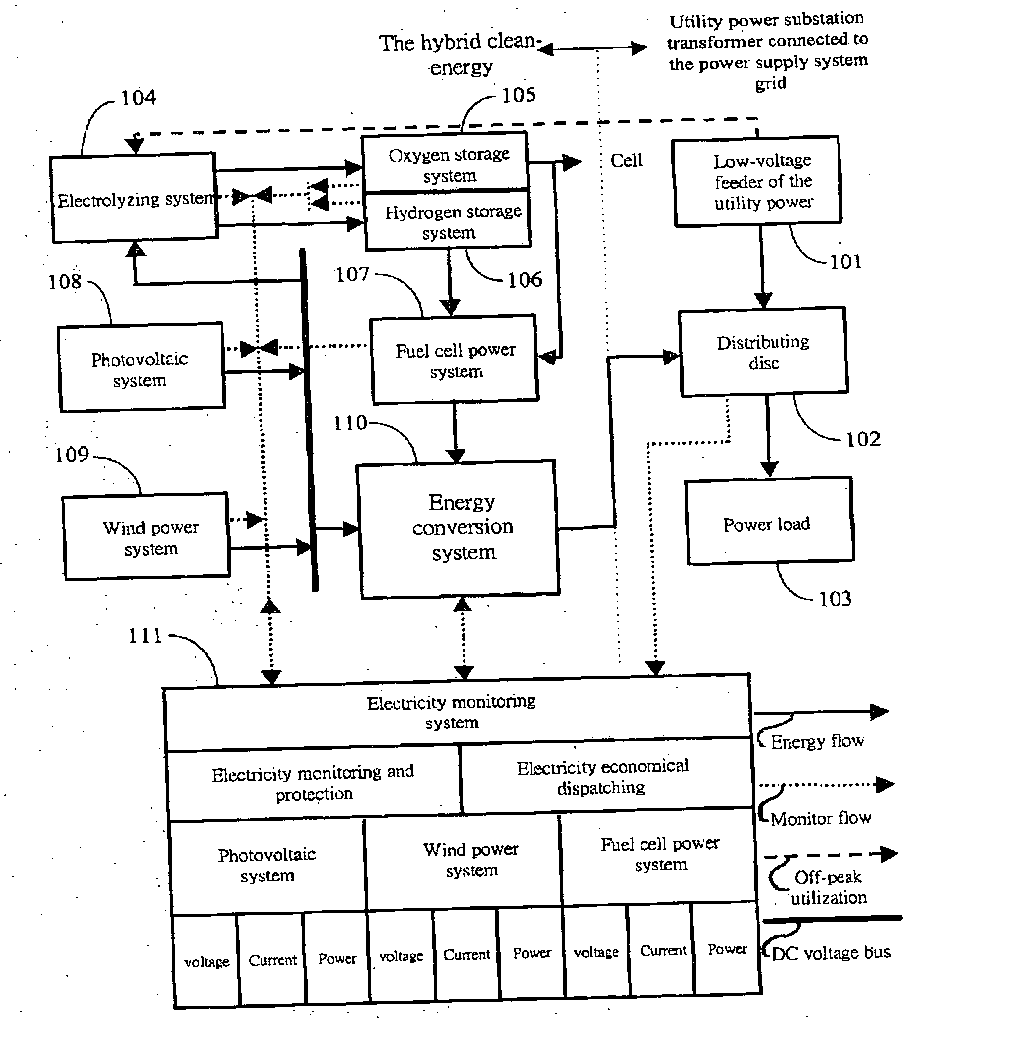
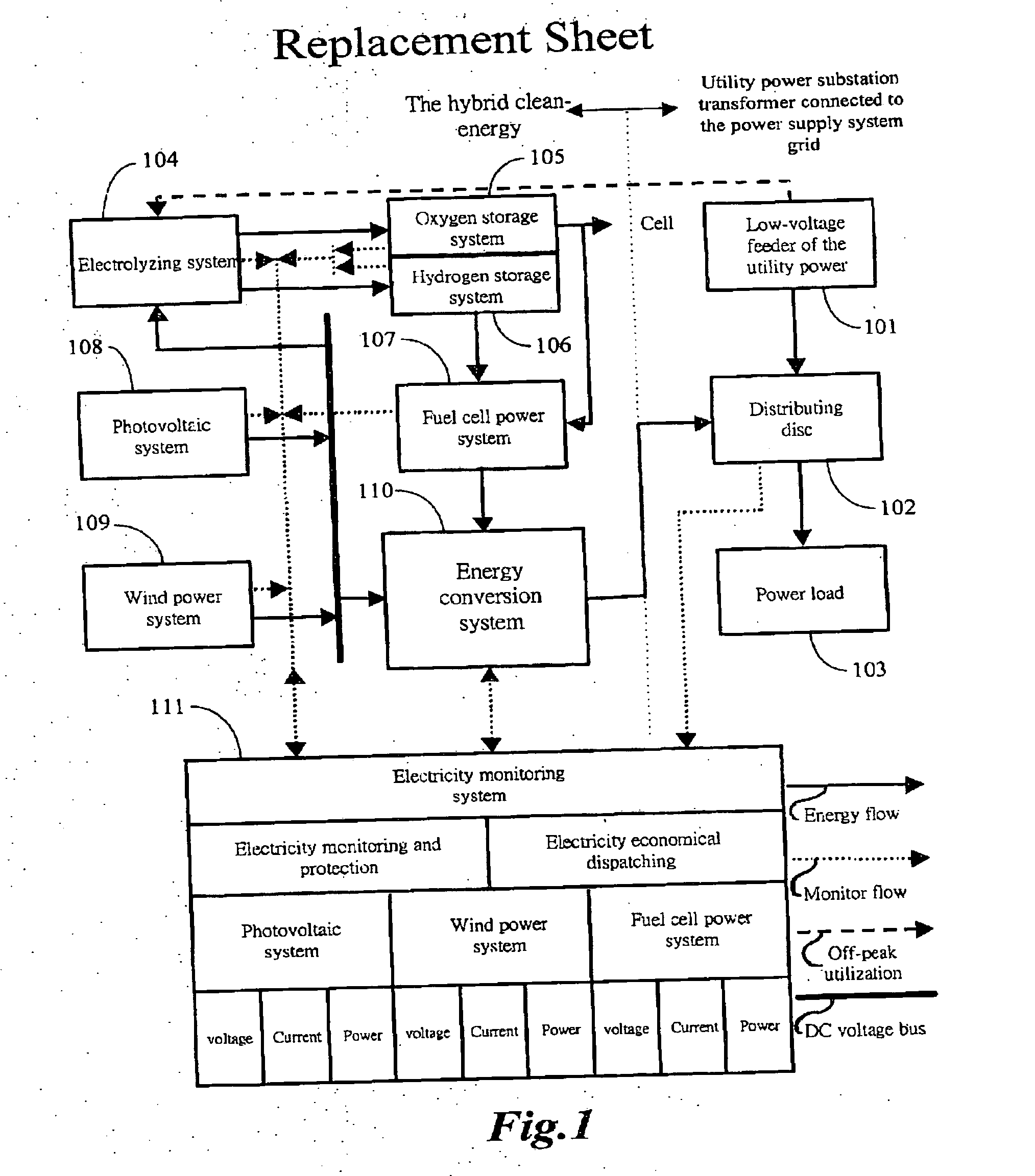
[0021]FIG. 1 shows a block diagram of a hybrid clean-energy power-supply framework according to the present invention. Said power-supply system includes an interface for feeding utility power. A general high-voltage client, stepping down the utility power in a transformer of a self-installed distribution substation to get a low-voltage feeder 101 for distribution, through a distributing disc 102, allocates shunts to each load. The distributing disc 102 comprises: a no-fuse breaker for preventing the conductive wire of the shunt from short-circuit; an electromagnetic switch for controlling the coil of said electromagnetic switch to make / break a shunt thereof and a control signal thereof touch-controlled by a digital switch of a central processing unit; a potential transformer (P.T.) and a current transformer (C.T.) for sending the sensed voltage and current of a shunt to a central processing unit for calculation. The distributing disc 102 has functions for protecting shunt lines and ...


PUM


Abstract

A hybrid clean-energy power-supply framework integrates a fuel cell, solar cell, and wind energy, applies a max power tracking rule, raises the output power of a solar cell and wind energy to supply a power load and transfer the surplus electrical energy to a water-electrolyzing apparatus for producing hydrogen and oxygen, and provides a fuel for a fuel cell power generating system. Furthermore, the present invention utilizes features of each clean-energy power generating system, depends on the powerful calculation capacity of a central processing unit to monitor and dispatch each power generation and supply system, and thus ensures the reliability of supply power and reduces the power generation cost. Such a framework can selectively grid-connect with the utility power or run as a stand-alone power supply system and has a mechanism for preventing the island effect.

Description

BACKGROUND OF THE INVENTION [0001] 1. Field of the Invention [0002] The present invention relates to a hybrid clean-energy power-supply framework, particularly to a hybrid clean-energy power-supply framework that integrates a fuel cell, photovoltaic, and wind energy into green-energy. [0003] 2. Description of the Prior Art [0004] In recent years, developing alongside a global rise in environmental consciousness and the problem of greenhouse effect brought by carbon dioxide pollution, the application of renewable energy becomes a noticeable issue and the sustainable development concept further becomes the major motive force of clean-energy promotion. [0005] A fuel cell, dependent on an electrochemical reaction to generate electrical energy without combustion, using hydrogen and oxygen to produce an electron flow for generating an electrical current, water, and heat, produces almost no pollution. The function of a fuel cell is similar to a battery but different, that is, electricity g...

Claims


Application Information

Patent Timeline
IPC IPC(8): F01B21/04F01K15/00F01K23/00F02B73/00
CPCF01K13/02F01K13/00
Inventor WAI, RONG-JONGDUAN, ROU-YONG
Owner YUAN ZE UNIV
Why Eureka
Try Eureka