Disc sliding mechanism

a disc sliding and disc technology, applied in the direction of brake discs, slack adjusters, braking elements, etc., can solve the problem of decelerating the connected wheel and consequently the vehicl

Inactive Publication Date: 2005-09-15
MERITOR HEAVY VEHICLE BRAKING SYST (UK) LTD
View PDF7 Cites 19 Cited by
  • Summary
  • Abstract
  • Description
  • Claims
  • Application Information

AI Technical Summary

Problems solved by technology

Frictional engagement of the brake disc with the brake pads causes deceleration of the clamped disc and therefore decelerates the connected wheel and consequently the vehicle.

Method used


Image

  • Disc sliding mechanism
  • Disc sliding mechanism
  • Disc sliding mechanism

Examples


second embodiment

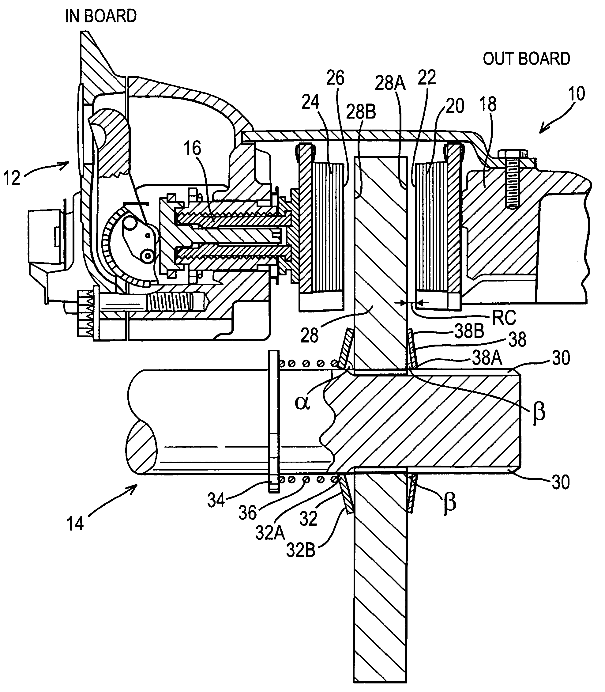
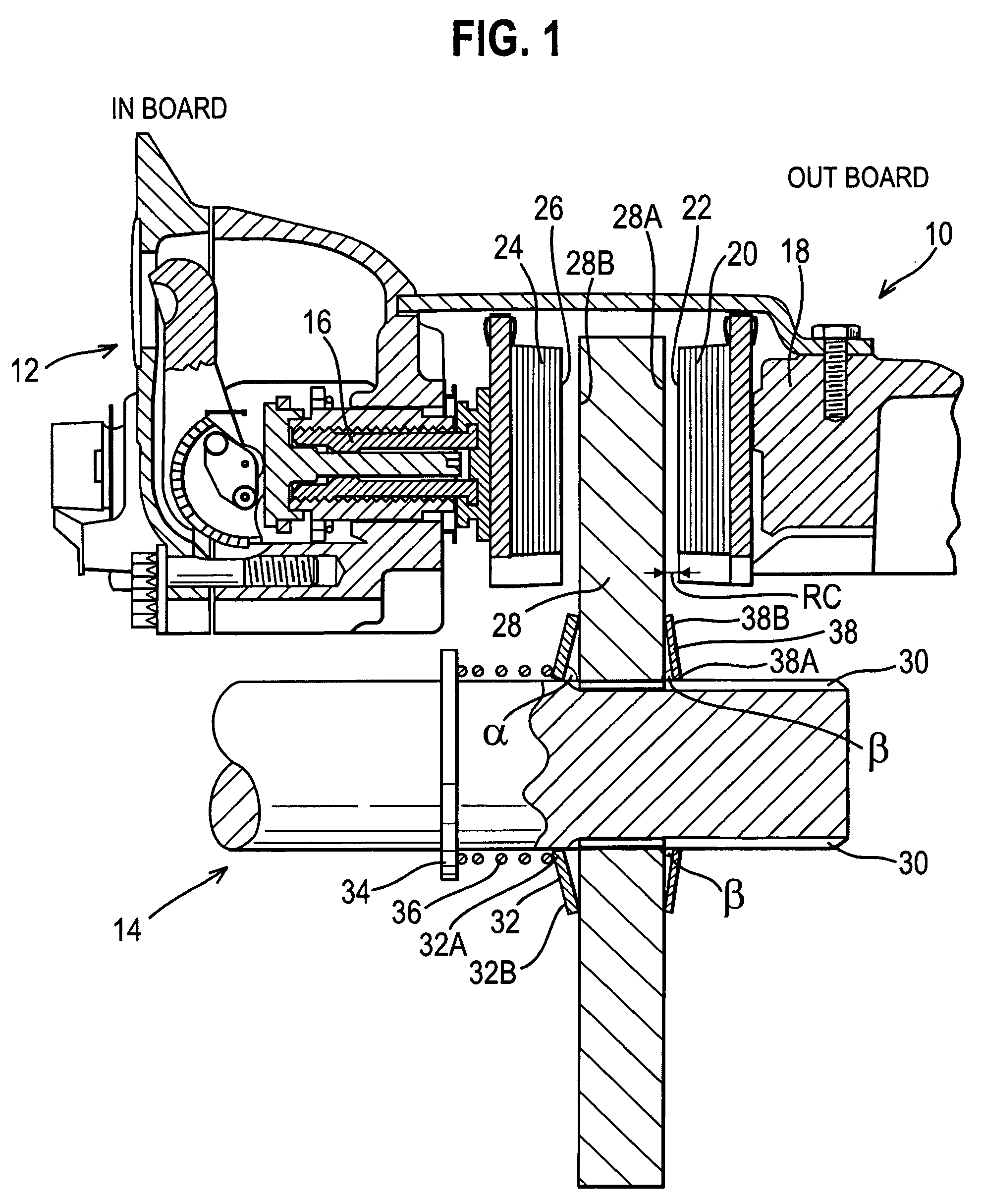
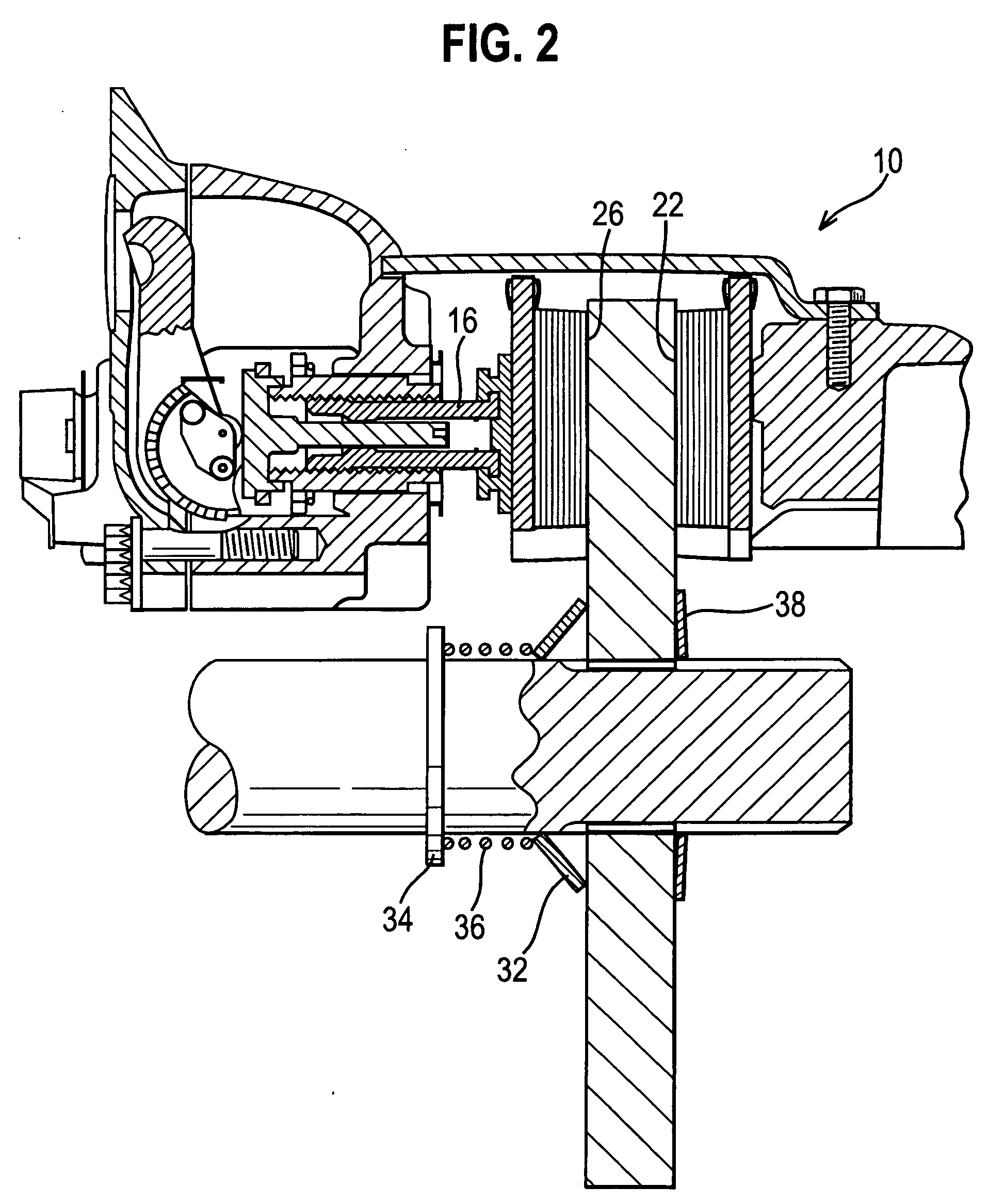
[0048] brake disc system of 110 is shown in FIG. 5, with the brake applied. Substantially identical components which have substantially the same function as components in the brake disc system 10 are given corresponding reference numbers, except with a prefix of 1.

[0049] In FIG. 5, a brake disc 128 is shown in a brake position and is clamped between brake pads 120 and 124. The brake disc system 110 does not have an inner spragging device and instead includes a moveable sleeve 140 in contact with a first face 128A of the brake disc 128. A biasing spring 136 is disposed between the movable sleeve 140 and a fixed sleeve 134. When in a brake off position (not shown), movement of the brake disc 128 in the inboard direction is reduced by the biasing spring 136.

[0050] A positioning device (disc positioner) 142 is located on the outboard side of the brake disc 128 instead of an outboard spragging device. The positioning device 142 is slidable on a shaft 114 and contacts a first face 128A o...

fourth embodiment

[0069] A cross sectional view of part of a brake disc system 310 according to the invention is shown in FIG. 9. FIG. 9 illustrates the cross section of the interface between a moveable brake disc 328 and a shaft 314. Substantially identical components with substantially the same function as components in the brake disc system 10 are given the same reference number, but with a prefix of 3.

[0070] The moveable brake disc 328 has an inner surface 360 including a series of pairs of splines 362 located around a circumference. A gap 364 between each pair of splines 362 is larger than a gap between each of the splines 362 that make up each pair.

[0071] The shaft 314 has an outer surface including a series of shaft splines 366 that each cooperate with a corresponding pair of splines 362 on the brake disc 328. Complaint members 370 are located in the gaps 364 between the pairs of splines 362. The compliant members 370 are wedged between the brake disc 328 and the shaft 314, reducing any rotat...

fifth embodiment

[0083]FIG. 12 shows the interface between a brake disc 428 and a shaft 414 of a brake disc system 400. Substantially identical components substantially the same function as components in the brake disc system 310 are given the same reference number, but with a prefix of 4 instead of 3.

[0084] A compliant member 470 has a lower arm 472 and an upper arm 474 connected by a hinge 476 and a connecting portion 490. The two arms 472 and 474 are resiliently biased apart and have been partly compressed together to be inserted between the brake disc 428 and the shaft 414. Consequently, the complaint member 470 exerts a radial force on the brake disc 428.

[0085] The arms 472 and 474 of each compliant member 470 are located in similar or identical positions to the compliant members 370 and therefore the view shown in FIG. 9 applies to the brake disc system 400 also. A connecting portion 490 is substantially cylindrical and has a plurality of compliant members 470 attached at one end. As such, th...


PUM


Abstract

A brake system includes a brake disc having a first disc face and a second disc face on a first side and a second side, respectively, of the brake disc. The brake disc is mounted rotatably fast with but longitudinally slidable on a rotatable shaft. The brake disc is clampable between a first friction surface of a fixed brake pad positioned on the first side of the brake disc and a second friction surface of a moveable brake pad positioned on the second side of the brake disc. The system further includes a disc positioner operable to define a running clearance between the first disc face and the first friction surface. The disc positioner is adjustable to maintain the running clearance as the fixed brake pad wears. A biasing member located on the second side of the brake disc maintains contact between the disc positioner and first disc face of the brake disc.

Description

REFERENCE TO RELATED APPLICATIONS [0001] This application claims priority to Great Britain patent application GB 0329425.3 filed Dec. 18, 2003. BACKGROUND OF THE INVENTION [0002] This invention relates generally to brake systems, and more specifically to devices for positioning discs within brake systems. [0003] Most conventional disc brake systems have a fixed brake disc and a caliper configuration with a piston and a cylinder. The caliper includes a sliding bridge which slides on pins and a pair of brake pads. An outer brake pad is on an outboard end (wheel side) of the bridge, and an inner brake pad is on an inboard end (chassis side) of the bridge. The fixed brake disc is located between the outer brake pad and the inner brake pad and is fixed rotatably and axially fast with a shaft connected to a wheel. [0004] When the brake is operated, the piston engages and slides the inner brake pad along the bridge into contact with an inside face of the fixed brake disc. A reaction force ...

Claims


Application Information

Patent Timeline
Patent Type & Authority Applications(United States)
IPC IPC(8): F16D55/224F16D55/2265F16D65/12F16D65/54F16D65/56
CPCF16D55/224F16D55/226F16D65/54F16D65/567F16D2065/1396F16D2065/1364F16D2065/1368F16D2065/1388F16D2065/1392F16D2065/1348
Inventor WARD, ANDREW JOHNHOLL, FRANZ HELMUTTAYLOR, MARTIN PORSMCCANN, DENIS JOHNCATTANEO, STEFANONORMAN, MARK ANTHONYJACKSON, JONATHON LESLIE CHRISTOPHERHEINLEIN, CARL EDWARD
Owner MERITOR HEAVY VEHICLE BRAKING SYST (UK) LTD
Why Eureka
Try Eureka