Automatic choke

a choke valve and automatic technology, applied in the direction of heating types, electrical control, separation processes, etc., can solve the problems of insufficient opening of the choke valve, insufficient output, and tendency to over-choke, and achieve the effect of enhancing the starting performan

Active Publication Date: 2005-09-15
HONDA MOTOR CO LTD
View PDF6 Cites 22 Cited by
  • Summary
  • Abstract
  • Description
  • Claims
  • Application Information

AI Technical Summary

Benefits of technology

[0008] It is hence an object of the present invention to present an automatic choke capable of controlling the choke valve accurately and finely while following up the engine temperature.
[0014] According to the third aspect of the invention, when starting the stepping motor driven in open loop, it can be initialized securely. In particular, depending on whether the start opening degree of the choke valve is closer to the fully closed side or to the fully opened side from the reference opening degree, the stepping motor for driving the choke valve is initialized either at the fully closed side or at the fully opened side of the choke valve. That is, since the choke valve is positioned and initialized preliminarily at the start opening degree side, after initializing the stepping motor, the choke valve can be moved in a short time up to the start opening degree. Therefore, after manipulation for engine start, the choke valve can be immediately moved to the start opening degree, and the starting performance is enhanced.

Problems solved by technology

However, since the solenoid is controlled either in on or off state, near the end of the choke period, that is, when the necessary choke period is nearly over, it tends to be over-choke (insufficient opening of choke valve).
However, since the bimetal is poor in response to temperature changes, the choke releasing timing is delayed both when starting a cold engine and when restarting a warm engine, thus it only consumes time while sufficient output is not obtained.

Method used


Image

  • Automatic choke
  • Automatic choke
  • Automatic choke

Examples


Embodiment Construction

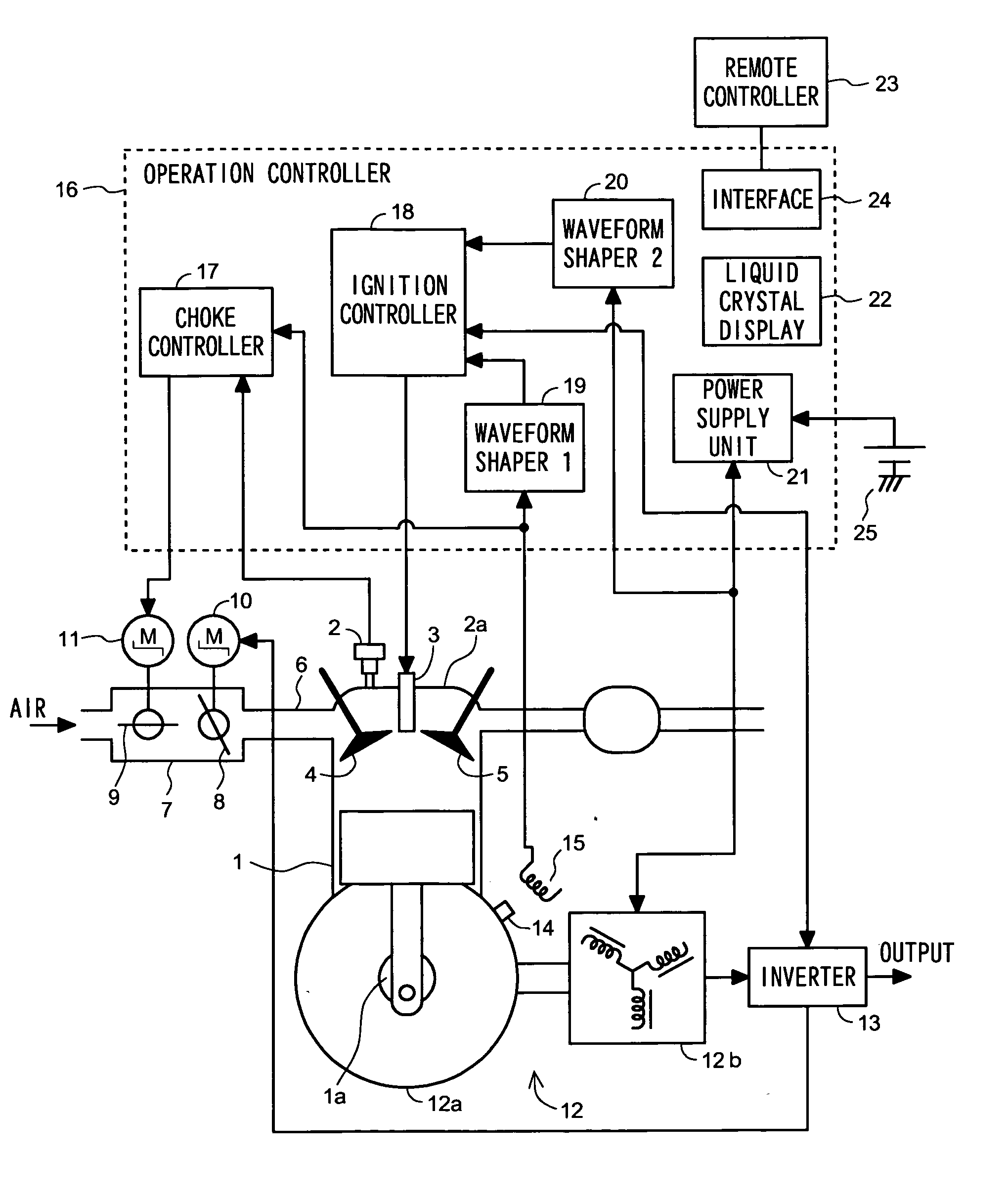
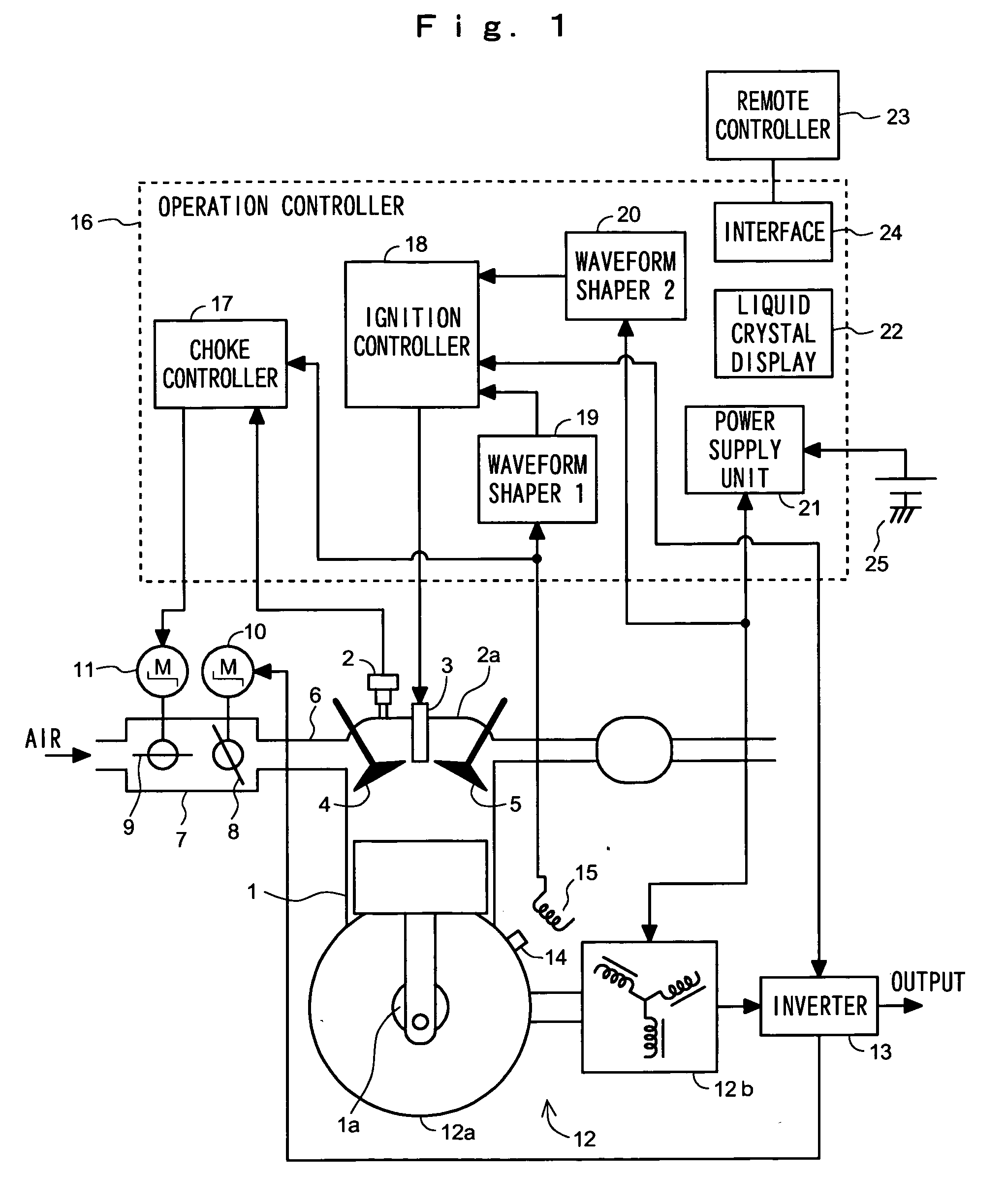
[0023] Referring now to the drawings, the invention is specifically described below. FIG. 1 is a block diagram of system configuration of an automatic choke in an embodiment of the present invention. In the diagram, an engine 1 is used as a driving source of a generator. The engine 1 includes a temperature sensor 2 for detecting the engine temperature. The temperature sensor 2 is provided, for example, on a cylinder head 2a. The cylinder head 2a includes an ignition plug 3, an intake valve 4, and an exhaust valve 5.

[0024] A carburetor 7 is connected to an intake tube 6 having the intake valve 4. The carburetor 7 includes a throttle valve 8 disposed at the downstream side, and a choke valve 9 disposed at its upstream. The throttle valve 8 is driven by a stepping motor 10 and opened or closed, and the choke valve 9 is driven by a stepping motor 11 and opened or closed.

[0025] The engine 1 is coupled to a generator 12. The generator 12 is driven by the engine 1, and generates alternat...


PUM

PropertyMeasurementUnit
frequencyaaaaaaaaaa
frequencyaaaaaaaaaa
temperatureaaaaaaaaaa

Abstract

A choke valve is controlled finely suited to the running state of an engine. A throttle valve 8 and a choke valve 9 are provided in series on an intake pipe 6, and the opening degree of the choke valve 9 is controlled by a stepping motor. The choke valve opening degree upon start of engine (start opening degree) is determined depending on the engine temperature. The stepping motor 11 is initialized at the fully closed side of the choke valve 9 when the power source for starting the engine is turned on. The start opening degree of the choke valve is judged to be closer to the fully closed side or fully opened side, and the stepping motor 11 is initialized at the fully closed side if judged to be close to the fully closed side, and at the fully opened side if at the fully opened side.

Description

BACKGROUND OF THE INVENTION [0001] 1. Field of the Invention [0002] The present invention relates to an automatic choke, and more particularly to an automatic choke capable of controlling air-fuel ratio favorably corresponding to temperature in the process of engine temperature rise after starting. [0003] 2. Description of the Related Art [0004] An automatic choke used when starting a cold engine is designed to control a solenoid actuator or diaphragm actuator for operating a choke valve according to the temperature detected by a temperature detecting element such as thermostat. When starting a cold engine, by controlling the air-fuel ratio in a direction of concentrating the mixed air by the automatic choke, the engine can be started stably. [0005] For example, Japanese Patent Application Laid-Open No. 5-280425 relates to a case of detecting a cold engine by a sensor composed of thermistor for issuing a detection signal corresponding to the temperature of the cylinder head, and dis...

Claims


Application Information

Patent Timeline
Patent Type & Authority Applications(United States)
IPC IPC(8): F02M1/08
CPCF02M1/08F02D41/067
Inventor KAMIMURA, KENJIASAI, KOUICHINAKAMURA, MASASHITAMURA, MINORUFUKUSHIMA, TOMOKI
Owner HONDA MOTOR CO LTD
Why Eureka
Try Eureka