Drum turning mechanism for continuous miners and longwall shearers

a technology of drum turning mechanism and longwall shearer, which is applied in the direction of pedestrian/occupant safety arrangement, driving means, vehicular safety arrangement, etc., can solve the problems of unsatisfactory machine service life, unfavorable customer service, and affecting the cutting performance of mining machines

Inactive Publication Date: 2005-09-22
JOY MM DELAWARE INC
View PDF4 Cites 20 Cited by
  • Summary
  • Abstract
  • Description
  • Claims
  • Application Information

AI Technical Summary

Benefits of technology

[0011] One of the principal objects of the invention is to provide a simple mechanism that permits turning of the cutting drum in a slow, easy manner so that cutting bits can be replaced.

Problems solved by technology

Dull, broken, or missing bits can have a serious impact on the cutting performance of a mining machine.
Such bits can also cause rough cutting, and rough cutting can place unnecessary stresses on the machine.
Both of these factors can lead to customer dissatisfaction with the machine.
Due to the difficulty in changing bits, operators frequently put off the chore well beyond the time the bits should optimally be changed.
A significant part of this difficulty is because of the difficulty in rotating the drums to provide access to the bits.
There are also safety concerns.
It is illegal in the USA for the main power to be applied to the machine when anyone is in the vicinity of the drums.
It is also difficult to control the amount of rotation.
This has the same concerns as (1), and if the cutter motors are accidentally energized, this can cause the machine to lurch suddenly.
Since the bit holders are usually wet and covered with residue, there is a potential for one or more of these people to fall in the area of the sharp bits.
The same concerns as (3) apply, plus there is a danger of leaving the bar in place when cutting resumes.
This was done in a laboratory environment but is unpractical underground due to the time to mount the winch and connect straps or cables each time the bits need to be changed and then stowing the winch afterward.

Method used


Image

  • Drum turning mechanism for continuous miners and longwall shearers
  • Drum turning mechanism for continuous miners and longwall shearers
  • Drum turning mechanism for continuous miners and longwall shearers

Examples


Embodiment Construction

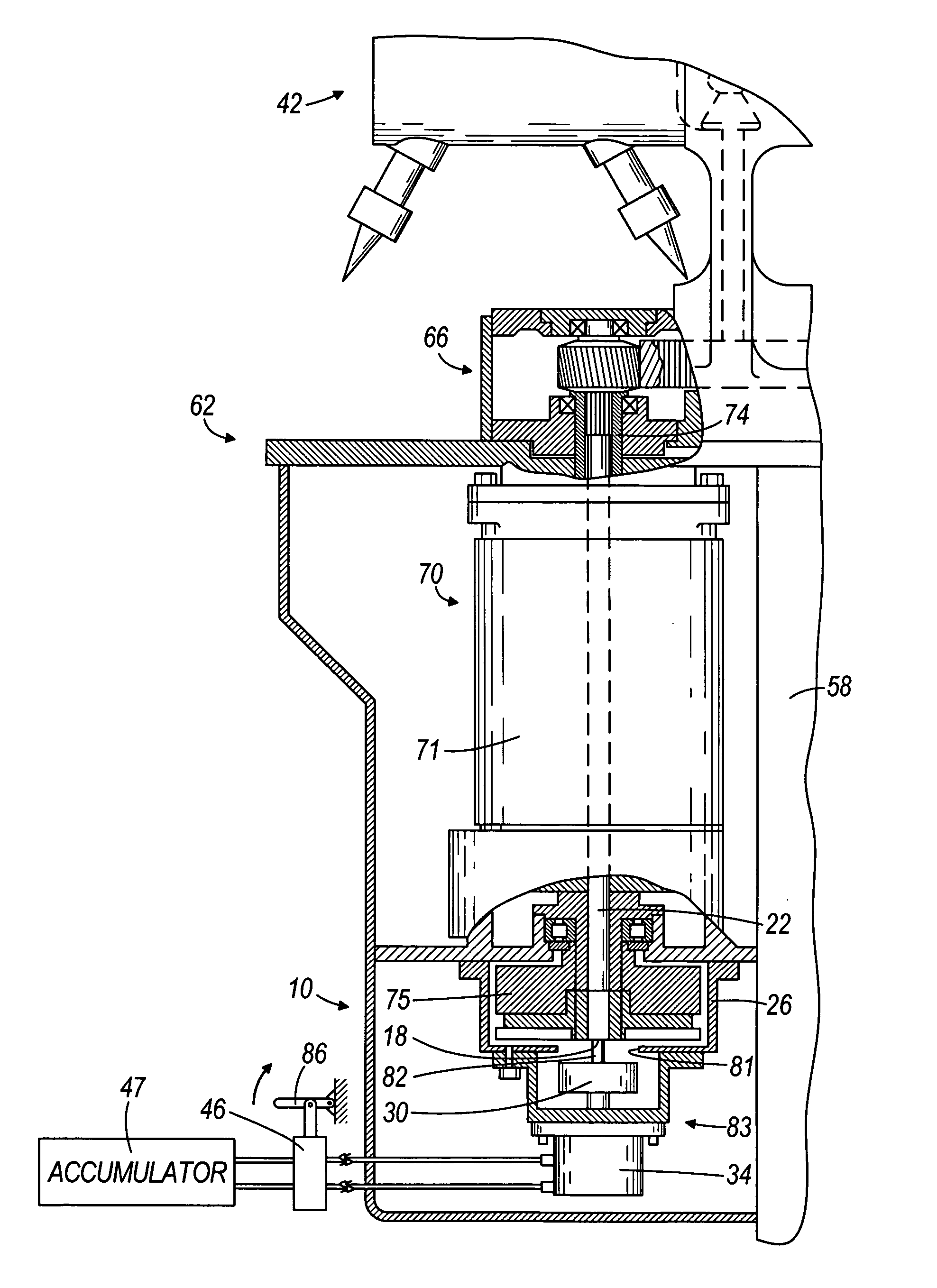
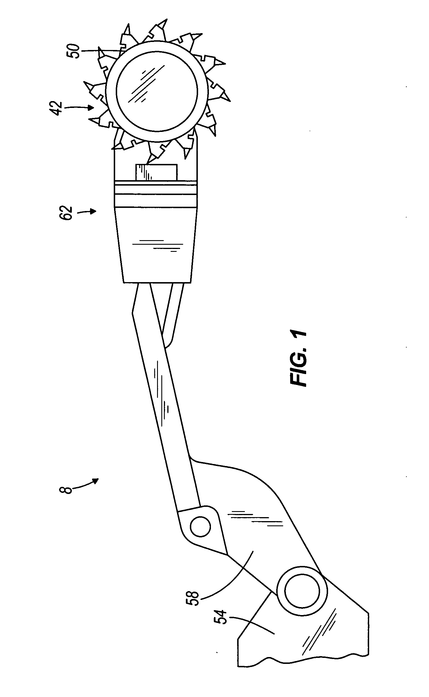
[0022] An embodiment of the invention is illustrated in FIGS. 1 and 2. More particularly, as shown in FIG. 1, the invention comprises a mining machine 8 (only part of which is shown) including a cutting drum 42, bits 50 mounted on the cutting drum 42, a base 54, and a boom 58 extending between the base 54 and the cutting drum 42 for mounting the drum 42 on the base 54. The mining machine 8 also includes a primary cutting drum turning mechanism 62 attached (indirectly in the illustrated embodiment) to the boom 58 and in driving connection with the cutting drum 42 for causing cutting movement of the cutting drum 42 at a cutting drum cutting speed.

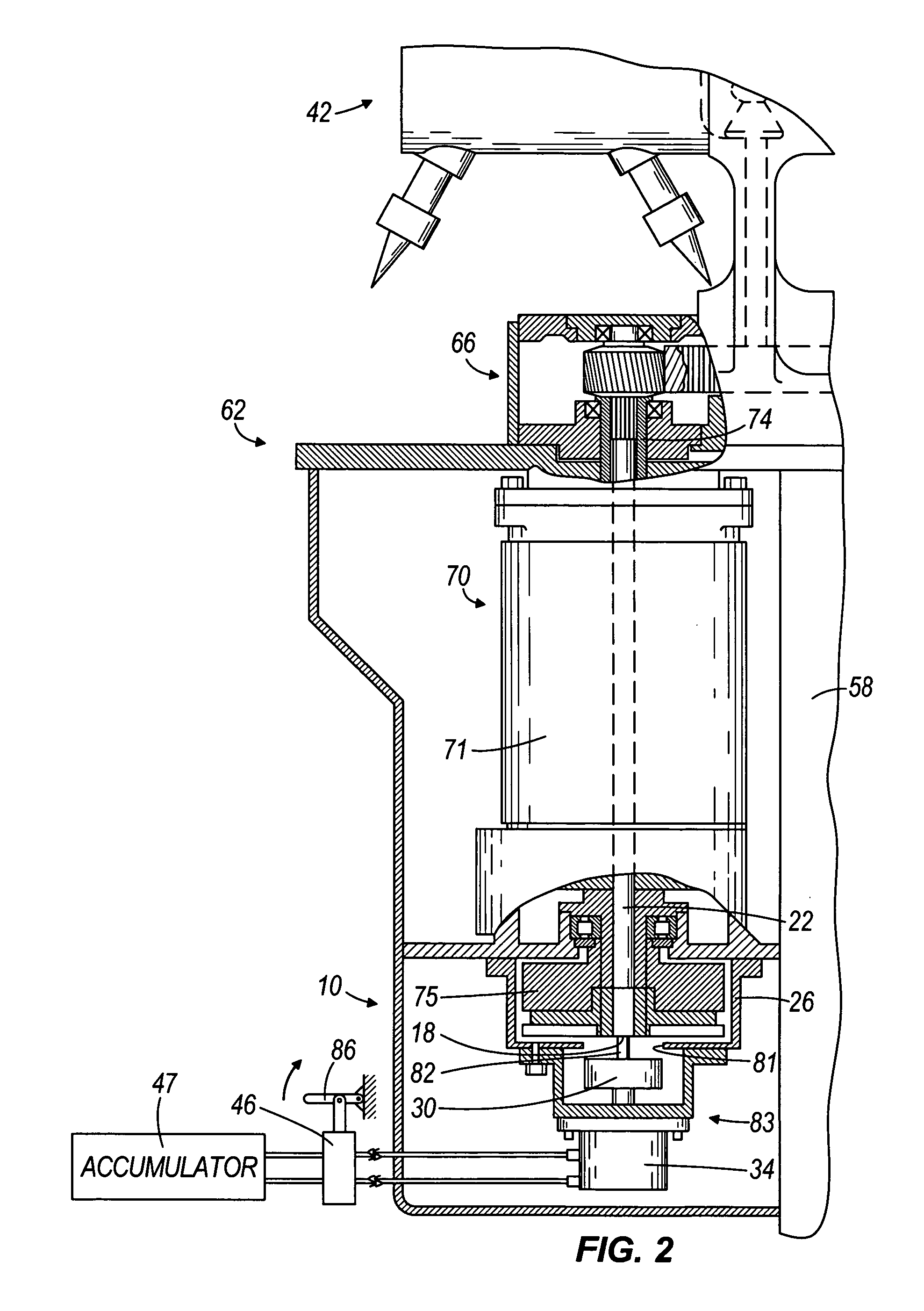
[0023] As illustrated in FIG. 2, the primary cutting drum turning mechanism 62 includes a gear case 66 attached to the boom 58, and a cutter motor 70. The cutter motor 70 is attached at one end to the gear case 66 and is in driving connection with the cutting drum 42 through the gear case 66.

[0024] The motor 70 further includes a motor hous...


PUM


Abstract

A mining machine including a cutting drum, a plurality of bits mounted on the cutting drum, a base, and a boom extending between the base and the cutting drum for mounting the drum on the base. The mining machine further includes a primary cutting drum turning mechanism attached to the boom and in driving connection with the cutting drum for causing cutting movement of the cutting drum at a cutting drum cutting speed, and a secondary cutting drum turning mechanism attached to the boom and in driving connection with the cutting drum for causing turning movement of the cutting drum at a speed much less than the cutting drum cutting speed.

Description

BACKGROUND OF THE INVENTION [0001] This invention relates to machines having cutting drums with bits mounted thereon, and, more specifically, to mechanisms for turning the cutting drums to permit bit removal. [0002] Dull, broken, or missing bits can have a serious impact on the cutting performance of a mining machine. Such bits can also cause rough cutting, and rough cutting can place unnecessary stresses on the machine. Both of these factors can lead to customer dissatisfaction with the machine. [0003] Due to the difficulty in changing bits, operators frequently put off the chore well beyond the time the bits should optimally be changed. A significant part of this difficulty is because of the difficulty in rotating the drums to provide access to the bits. There are also safety concerns. It is illegal in the USA for the main power to be applied to the machine when anyone is in the vicinity of the drums. [0004] The current methods of turning a drum to replace the bits include: [0005]...

Claims


Application Information

Patent Timeline
Patent Type & Authority Applications(United States)
IPC IPC(8): E21BE21CE21C25/08E21C31/02E21C37/00E21D9/10
CPCE21D9/1013E21C31/02
Inventor O'NEILL, MICHAEL L.
Owner JOY MM DELAWARE INC
Why Eureka
Try Eureka