Sim, sim holder, ic module, ic card and ic card holder
a technology of sim which is applied in the field of sim card, ic module, ic card and ic card holder, can solve the problems of large attachment, inability to form, and inability to manufacture key holder type id modules, and achieve the same procedures as conventional ic cards, and the effect of large attachmen
- Summary
- Abstract
- Description
- Claims
- Application Information
AI Technical Summary
Benefits of technology
Problems solved by technology
Method used
Image
Examples
first embodiment
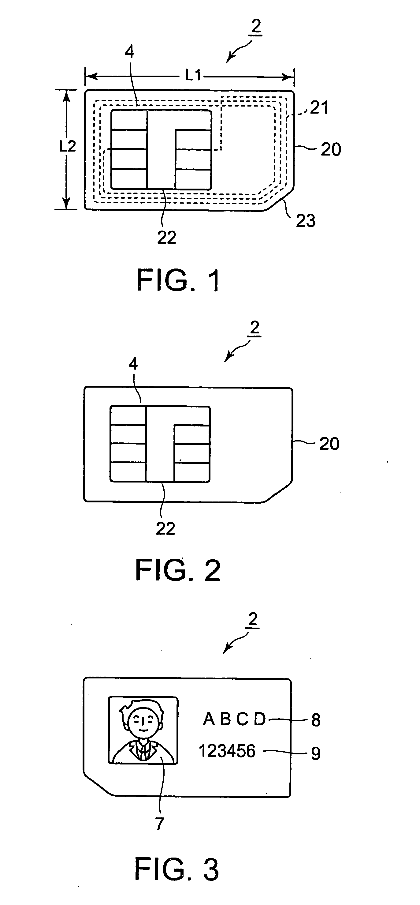
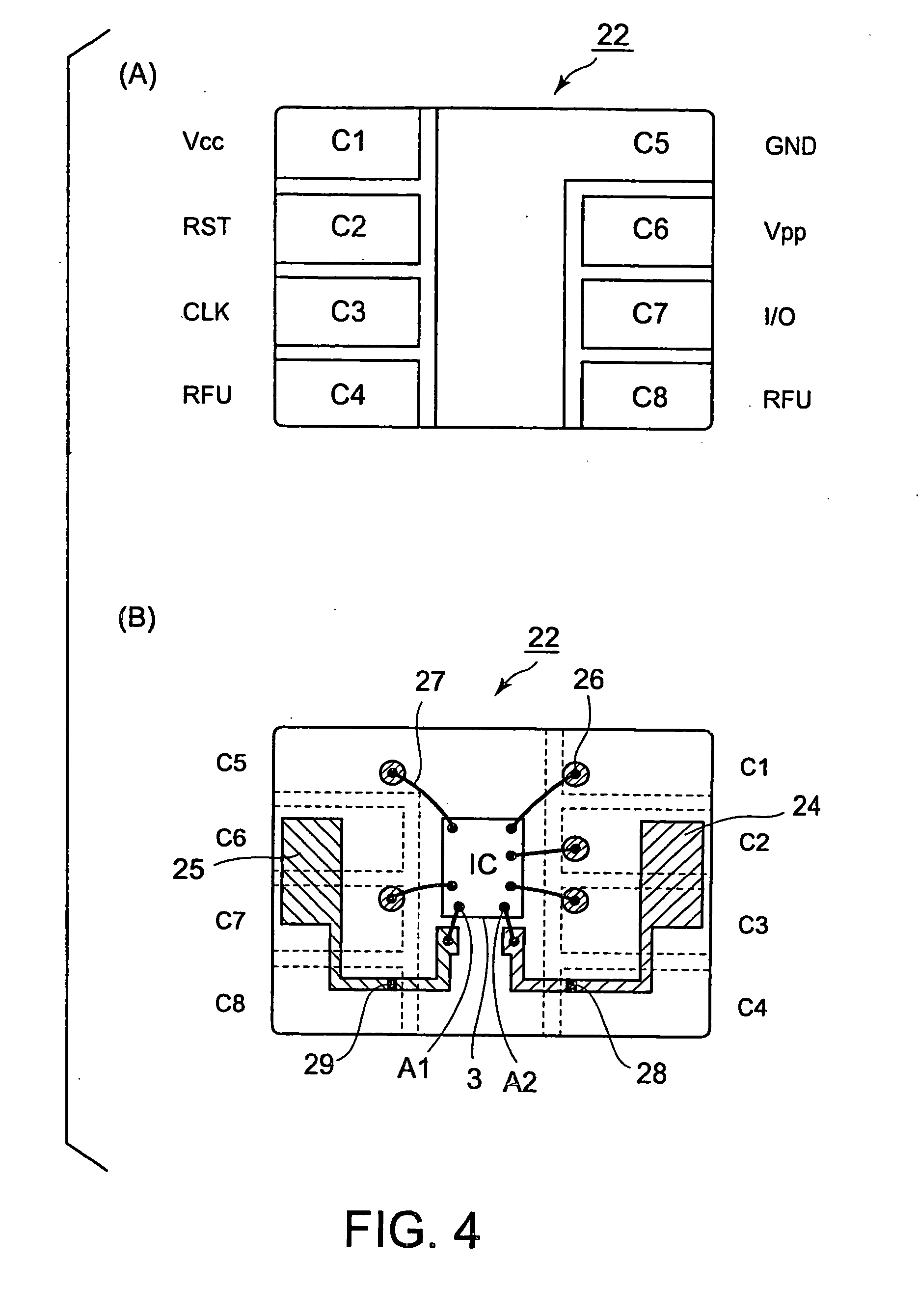
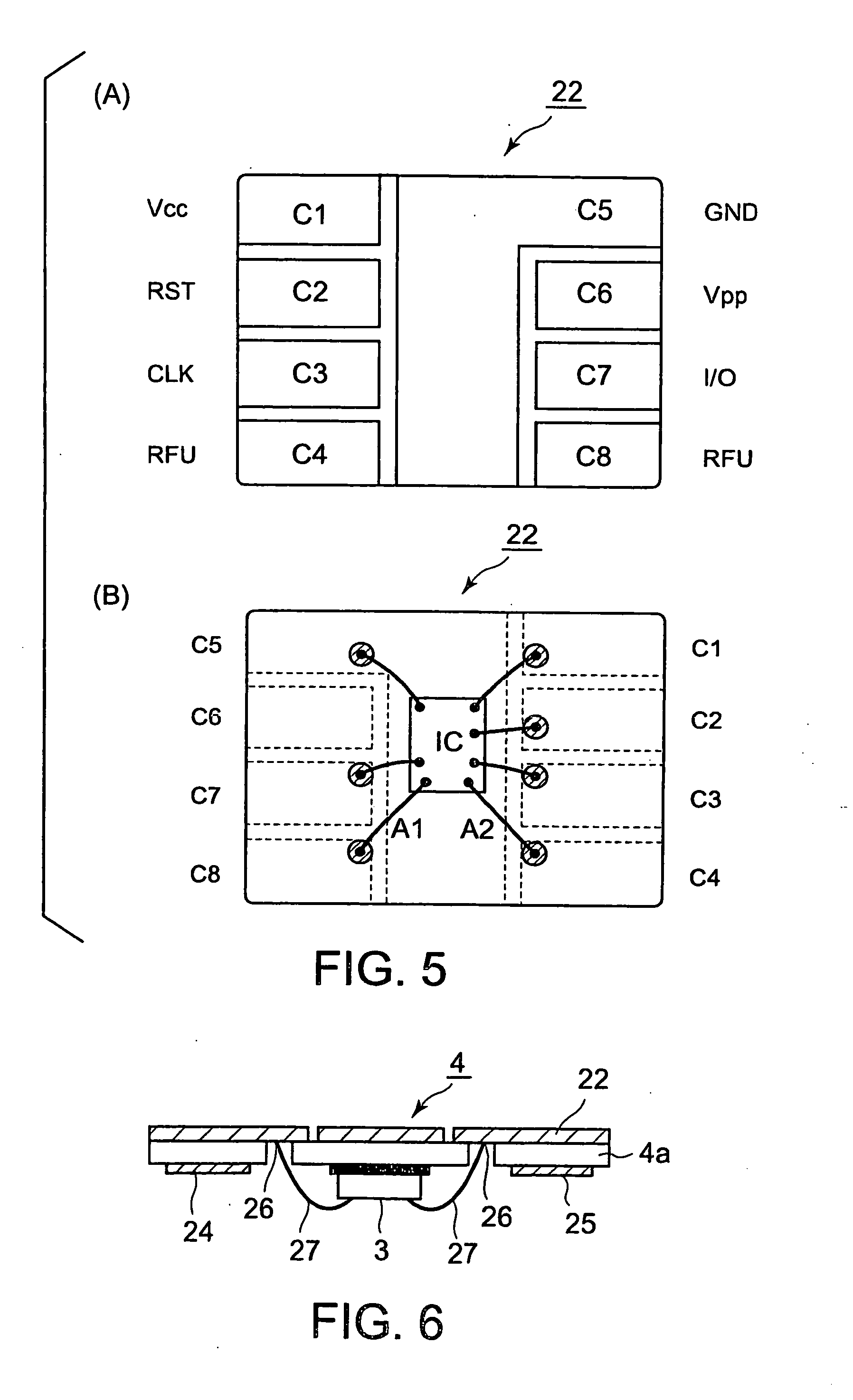
[0137] The present invention relates to a SIM and a SIM holder. First, a SIM, i.e., an ID module, employed in the present invention will be described.
[0138] A SIM (ID module) employed in the present invention is the aforesaid SIM, UIM or USIM (hereinafter, “SIM” will be used as the general term for ID modules including UIMs and USIMs in the following description and claims) provided with an IC chip for contact and noncontact uses, i.e., an IC chip provided with a dual interface, and some embodiments employs an IC chip further provided with an antenna coil for noncontact communication.
[0139] The conventional contact SIM communicates with a PDA (personal digital assistant) in a contact communication mode through a terminal plate connected to the terminals of the PDA. The SIM of the present invention differs from the conventional contact SIM in communication mode.
[0140] The SIM (ID module) employed in the present invention to be used also as a prepaid card and a card for using trans...
second embodiment
[0199] The present invention relates to a SIM and a SIM holder. First, a SIM, i.e., an ID module, employed in the present invention will be described.
[0200] A SIM (ID module) employed in the present invention is the aforesaid SIM, UIM or USIM (hereinafter, “SIM” will be used as the general term for ID modules including UIMs and USIMs in the following description and claims) provided with an IC chip for both contact and noncontact uses, i.e., an IC chip provided with a dual interface.
[0201] The term “SIM” will be used as the general term for small ID modules of sizes corresponding to those of plug-in SIMs specified in GSM.1111 or 3GPPTS11.11. The function of the SIM is not limited to that of the aforesaid subscriber identification device for a portable telephone. Sometimes, the term “UIM” will be used instead of “SIM”.
[0202] The second embodiment of the present invention will be described with reference to the accompanying drawings.
[0203]FIG. 12 is a view of a SIM in a second emb...
third embodiment
[0263] As mentioned above, the present invention relates to an IC module provided with three kinds of interfaces (sometimes, referred to as “IC module of the present invention”), a three-way SIM and a SIM holder, a three-way IC card and an IC card holder. First, an IC module of the present invention will be described.
[0264]FIG. 22 is view of assistance in explaining an IC chip to be included in an IC module in a third embodiment according to the present invention, FIG. 23 is a view of assistance in explaining the relation between the terminals (pads) of the IC chip and a contact-terminal plate.
[0265]FIG. 24 is a view of an IC module in Example 3-1, FIG. 25 is a view of an IC module in Example 3-2, FIG. 26 is a view of an IC module in Example 3-3, FIG. 27 is a view of an IC module in Example 3-4 and FIG. 28 is a view of an IC module in Example 3-5.
[0266] An IC module 204 of the present invention has a substrate 204a, an IC chip 203 mounted on the substrate 204a, and a contact-term...
PUM
 Abstract
Description
Claims
Application Information
 - R&D
- Intellectual Property
- Life Sciences
- Materials
- Tech Scout
- Unparalleled Data Quality
- Higher Quality Content
- 60% Fewer Hallucinations
Browse by: Latest US Patents, China's latest patents, Technical Efficacy Thesaurus, Application Domain, Technology Topic, Popular Technical Reports.
© 2025 PatSnap. All rights reserved.Legal|Privacy policy|Modern Slavery Act Transparency Statement|Sitemap|About US| Contact US: help@patsnap.com


