Snap ring with recessed interior contour

a technology of interior contour and snap ring, which is applied in the direction of screws, threaded fasteners, instruments, etc., can solve the problems of data loss, disk and head tribological failure, and interface tribological failur

Active Publication Date: 2005-09-29
INTRI PIEX TECH INC
View PDF22 Cites 21 Cited by
  • Summary
  • Abstract
  • Description
  • Claims
  • Application Information

AI Technical Summary

Problems solved by technology

However, because there is relative motion between the disk surface and the head due to the disk rotation and head actuation, continuous contact between the head and disk can lead to tribological failure of the interface.
Such tribological failure, known colloquially as a “head crash,” can damage the disk and head, and usually causes data loss.
In addition to tribological consequences, contamination and debris at or near the head disk interface can force the head away from the disk.
The resulting temporary increases in head-disk spacing cause magnetic read / write errors.
For example, the actuator arm can not be designed to be too massive because it must accelerate very quickly to reach information tracks containing desired information.
The industry's marked reliance on cleaning steps survives even though assembly in clean environments and post-assembly cleaning steps are not thorough in their removal of contaminants and debris.
Still, such consideration is often restricted to the selection of lubricants and adhesives.
Since only one of the faces of a conventional snap ring has stamping die roll, regardless of the snap ring's orientation one of its faces will be prone to generate debris (either through burnishing of the surface of the actuator arm structure or via contact with the pivot bearing sleeve).

Method used


Image

  • Snap ring with recessed interior contour
  • Snap ring with recessed interior contour
  • Snap ring with recessed interior contour

Examples


Embodiment Construction

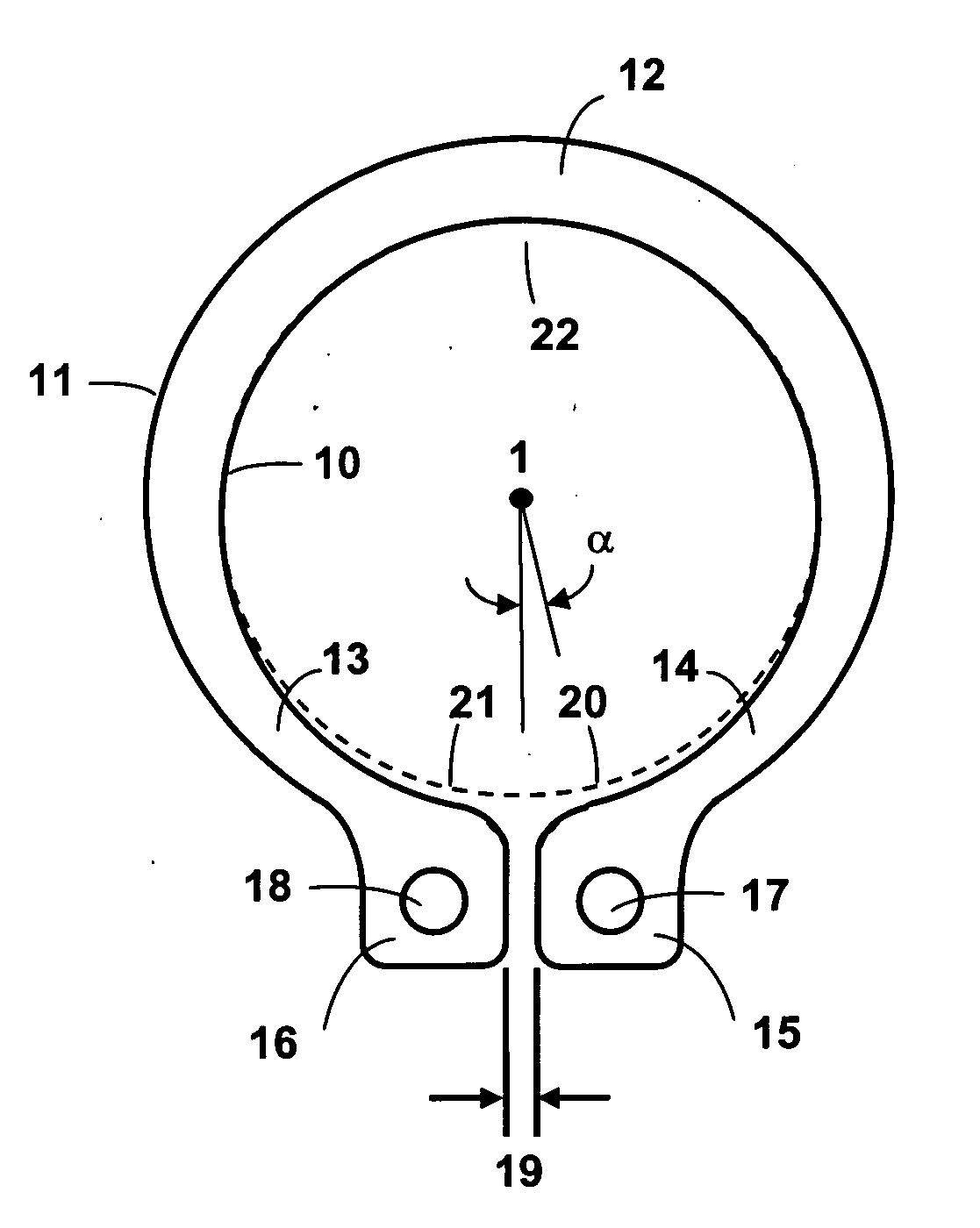
[0028] A snap ring for applications requiring cleanliness has a novel recessed interior contour that reduces debris generation during installation of the snap ring.

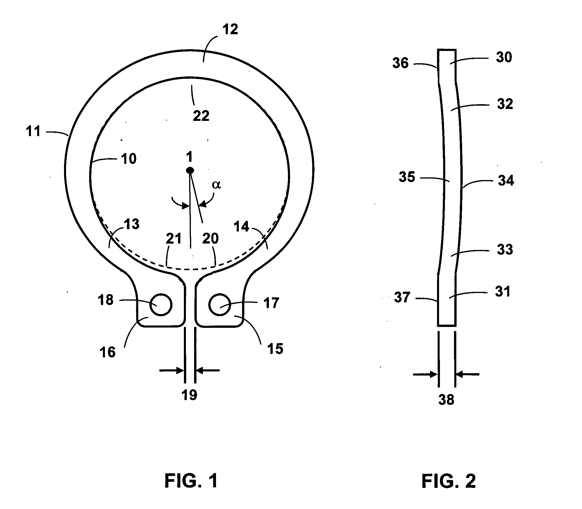
[0029]FIG. 1 shows a top view of an actuator pivot bearing snap ring according to an embodiment of the present invention, that illustrates several specific design features and associated nomenclature. The snap ring has an opening bounded by interior contour 10 and has an outer contour 11. In this embodiment, the width of the snap ring in hinge region 12 is wider than in neck regions 13 and 14. The snap ring terminates at two terminal regions 15 and 16 that may comprise tabs that include tooling holes 17 and 18, respectively. The snap ring is typically forcefully expanded during installation which temporarily increases the circumferential gap 19 between the terminal regions 15 and 16. The forceful expansion also causes the interior contour 10 to temporarily deform.

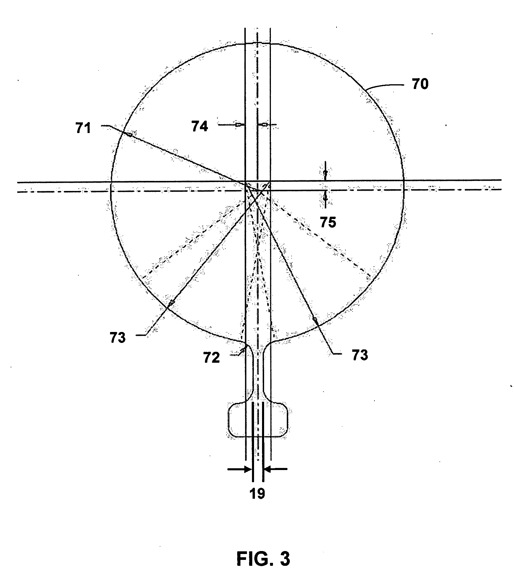
[0030] In the embodiment of FIG. 1, the interior contour ...


PUM

PropertyMeasurementUnit
bevel angleaaaaaaaaaa
radiusaaaaaaaaaa
widthaaaaaaaaaa

Abstract

A snap ring for applications requiring cleanliness has a novel recessed interior contour that reduces debris generation during installation of the snap ring. The snap ring is suitable for applications where a reduction in debris generation is desirable, such as to retain an actuator pivot bearing in information storage devices like magnetic hard disk drives.

Description

BACKGROUND OF THE INVENTION [0001] 1. Field of the Invention [0002] This invention relates generally to snap rings designed for use in clean environments and particularly to snap rings for use in information storage devices. [0003] 2. Background Information [0004] In hard disk drives, magnetic heads read and write data on the surfaces of co-rotating disks that are co-axially mounted on a spindle motor. The magnetically-written “bits” of written information are therefore laid out in concentric circular “tracks” on the surfaces of the disks. The disks must rotate quickly so that the computer user does not have to wait long for a desired bit of information on the disk surface to translate to a position under the head. In modern disk drives, data bits and tracks must be extremely narrow and closely spaced to achieve a high density of information per unit area of the disk surface. [0005] The required small size and close spacing of information bits on the disk surface has consequences on...

Claims


Application Information

Patent Timeline
Patent Type & Authority Applications(United States)
IPC IPC(8): F16B21/18G11B33/14
CPCG11B33/1446F16B21/18
Inventor DEXTER, DAVID DJANGOBRINK, DAMON DOUGLASSCHMIDT, RYAN JOHNSPRANKLE, MATTHEW S.HANRAHAN, KEVIN PATRICK
Owner INTRI PIEX TECH INC
Why Eureka
Try Eureka