Magnetoelectric devices and methods of using same

a technology of magnetoelectric devices and magnetic field, applied in piezoelectric/electrostrictive/magnetostrictive devices, device material selection, etc., can solve the problems of limiting sensitivities, reducing the bandwidth of induced bandwidth to about 30 khz, and disappearing voltage signals into nois

Active Publication Date: 2005-10-06
THE HONG KONG POLYTECHNIC UNIV
View PDF3 Cites 21 Cited by
  • Summary
  • Abstract
  • Description
  • Claims
  • Application Information

AI Technical Summary

Benefits of technology

[0007] Therefore, it is an object of this invention to provide a magnetoelectric device and magnetoelectric composite that may reso...

Problems solved by technology

However, the lower the signal frequency (i.e., the lower the flux change rate), the longer the integration time is required, and below a certain signal frequency, the voltage signal disappears into the noise.
Although Hall-effect devices do not suffer from these problems, they have limited sensitivities (i.e., 5-50 μV/Oe) and are always hampered by a noise-induced bandwidth limitation to about 30 kHz.
While these sintered bulk materials generally show a higher magnetoelectric voltage coefficient (i.e., αE˜0.13 V/cm·Oe, where αE=dE/dH is the ratio of the change in electric field strength to the change in magnetic field strength) than single-phase materials (i.e., ˜0.02 V/cm·Oe for Cr2O3), they still have some crucial problems in reproducibility and reliability impeding their commercial viability.
These problems include: 1) difficulties in machining and fabricating devices due to the brittleness of the materials; 2) difficulties in controlling the connectivity of the constituent phases; 3) chemical reaction between phases during high-temperature sintering; 4) dielectric breakdown through the low electrically resistant magnetostrictive phase during poling of the piezoelectric phase under a high electric poling field to induce an electric polarization; and 5) weak mechanical coupling between phases owing to processing-induced mechanical defects (i.e., pores, cracks, etc.).
As the development of magnetoelectric ma...

Method used


Image

  • Magnetoelectric devices and methods of using same
  • Magnetoelectric devices and methods of using same
  • Magnetoelectric devices and methods of using same

Examples


Embodiment Construction

[0030] This invention is now described by way of example with reference to the figures in the following paragraphs.

[0031] Objects, features, and aspects of the present invention are disclosed in or are obvious from the following description. It is to be understood by one of ordinary skill in the art that the present discussion is a description of exemplary embodiments only, and is not intended as limiting the broader aspects of the present invention, which broader aspects are embodied in the exemplary constructions.

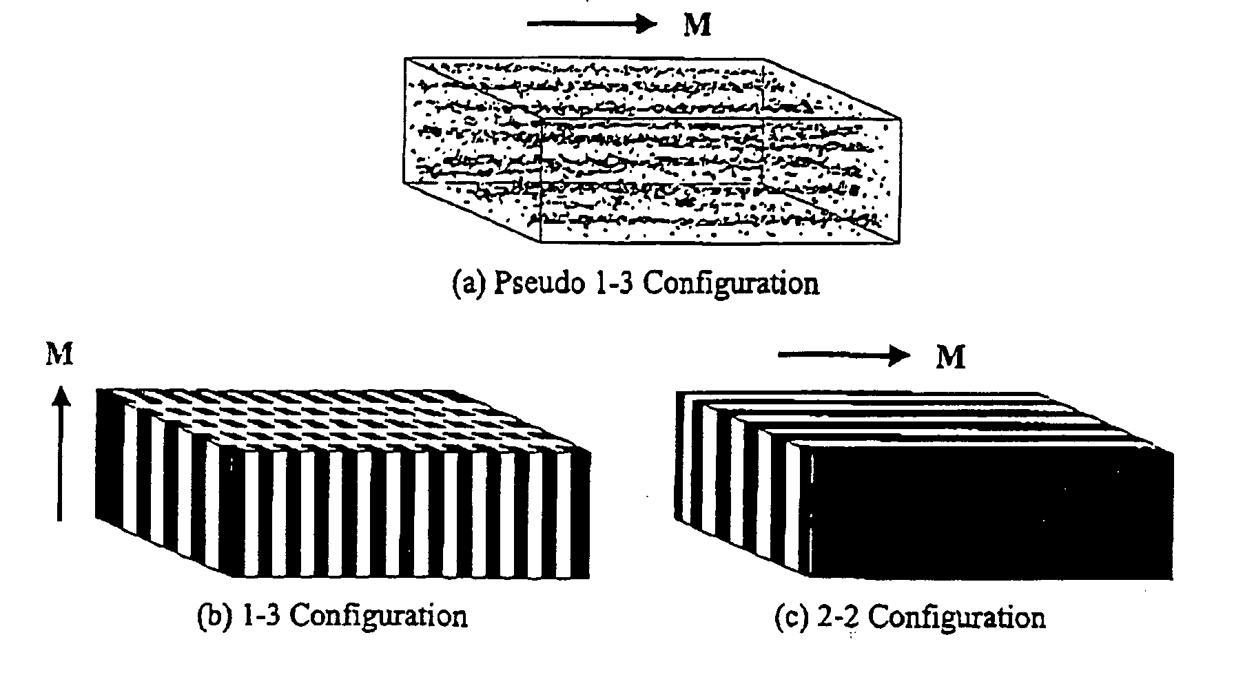
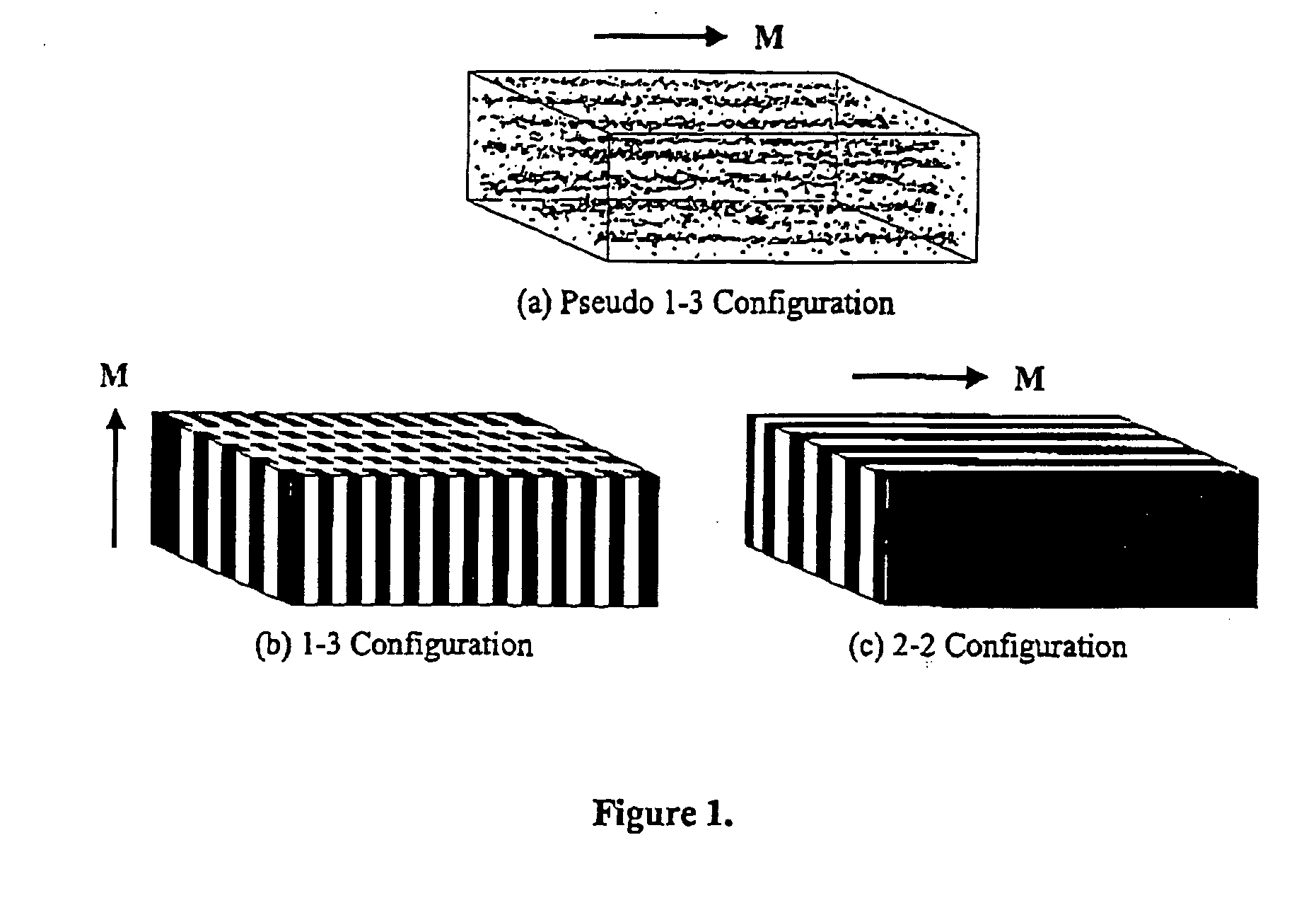
[0032]FIG. 1 shows different configurations of a low-eddy-current-loss, high-compliance magnetostrictive composite for the magnetoelectric devices according to the invention. The magnetostrictive composite is preferred to be made of a magnetostrictive material of rare-earth-based alloy [e.g., terbium-dysprosium-iron alloy (Terfenol-D), gallium-iron alloy (Gafenol), samarium-dysprosium-iron alloy (Samfenol-D), etc.] dispersed in a polymer matrix that is passive to magnet...


PUM


Abstract

Existing magnetoelectric materials relying on the use of metallic or ceramic magnetostrictive materials and ceramic piezoelectric materials as their constituent phases may have three problems. First, the operational frequency may be limited to a few kilohertz due to the presence of eddy-current losses in the metallic magnetostrictive phase. Secondly, it may be difficult to machine and fabricate devices due to the mechanical brittleness of the ceramic and some metallic magnetostrictive phases as well as of the ceramic piezoelectric phase. Thirdly, it may be difficult to tailor and optimize the properties (i.e., magnetoelectric voltage coefficient αE, etc.) of the devices due to the limitation of the types of the constituent materials. This invention provides a magnetoelectric element including at least one set of alternative piezoelectric layer and magnetostrictive composite layer. The magnetostrictive composite layer includes at least one magnetostrictive material dispersed in first concentrated zones within a first polymer matrix, wherein all of said concentrated zones are orientated along a first direction. It is found that the conversion efficiency (i.e., αE) varies in accordance with applied magnetic control field Hcontrol in magnetoelectric devices made of such a magnetoelectric element.

Description

FIELD OF THE INVENTION [0001] This invention relates to magnetoelectric devices, particularly those incorporating magnetostrictive composite. BACKGROUND OF THE INVENTION [0002] Common magnetic-field sensors for converting magnetic field to electric field signals include reluctance coils and Hall-effect devices. Reluctance coils generate an electric voltage proportional in magnitude to the time rate of change of magnetic flux coupling within the coils. To obtain an accurate measurement, a highly precise, low-noise, low-drift electronic integrator may be required to integrate the voltage signal induced across the coil. However, the lower the signal frequency (i.e., the lower the flux change rate), the longer the integration time is required, and below a certain signal frequency, the voltage signal disappears into the noise. Although Hall-effect devices do not suffer from these problems, they have limited sensitivities (i.e., 5-50 μV / Oe) and are always hampered by a noise-induced bandw...

Claims


Application Information

Patent Timeline
IPC IPC(8): H01L41/06H01L41/16H02N2/00
CPCH01L41/16H10N30/85
Inventor OR, SIU WINGCHAN-WONG, HELEN LAI WA
Owner THE HONG KONG POLYTECHNIC UNIV
Why Eureka
Try Eureka