Screw and rod fixation assembly and device

a technology of fixing assembly and screw rod, which is applied in the field of orthopedic devices, can solve the problems of affecting the healing process of the spine, and affecting the ability of the screw to move in the direction of prosthesis,

Inactive Publication Date: 2005-10-13
RICHELSOPH MARC +1
View PDF17 Cites 205 Cited by
  • Summary
  • Abstract
  • Description
  • Claims
  • Application Information

AI Technical Summary

Benefits of technology

[0019] According to the present invention, there is provided a screw and rod fixation assembly for fixing a screw and a rod, the assembly having a screw including a screw head, a body portion including a screw head receiving device for receiving the screw head and a rod receiving device for receiving a rod therein, the rod receiving device being offset from the screw head receiving device, and a locking device for locking a rod within the rod receiving device. Also provided is a medical device for fixing a screw and a rod, the assembly having a screw including a screw head, a body portion having a receiver for receiving the screw head and an offset slot for receiving a rod therein, and a lock for locking the rod within the assembly. A receiving member for receiving and maintaining a rod therein, the receiving member having a body portion having a receiver for receiving a screw head and an offset slot for receiving a rod therein is provided. A rod receiving device having a body portion having a receiver for receiving a screw therein and a rod seat offset within the body portion is also provided.

Problems solved by technology

The spine anatomy, however, rarely allows for three or more implants to be directly in line.
Any movement of the screw can be detrimental towards the healing process of the spine.
Further, additional damage can occur if there is movement of the screw once it has been fixed to the vertebrae.
Typically, the more complex the locking mechanism requires larger components and manufacturing costs are expensive.
Locking and achieving strong hold values become more difficult with more parts.
Bulky components can cause soft tissue irritation, as well as compromise the facet joints at the end of a fusion.
Soft tissue irritation resulting from extensions of implants is a common occurrence.
For example, implants can be too large to be sufficiently covered within the muscle tissue.

Method used


Image

  • Screw and rod fixation assembly and device
  • Screw and rod fixation assembly and device
  • Screw and rod fixation assembly and device

Examples


Embodiment Construction

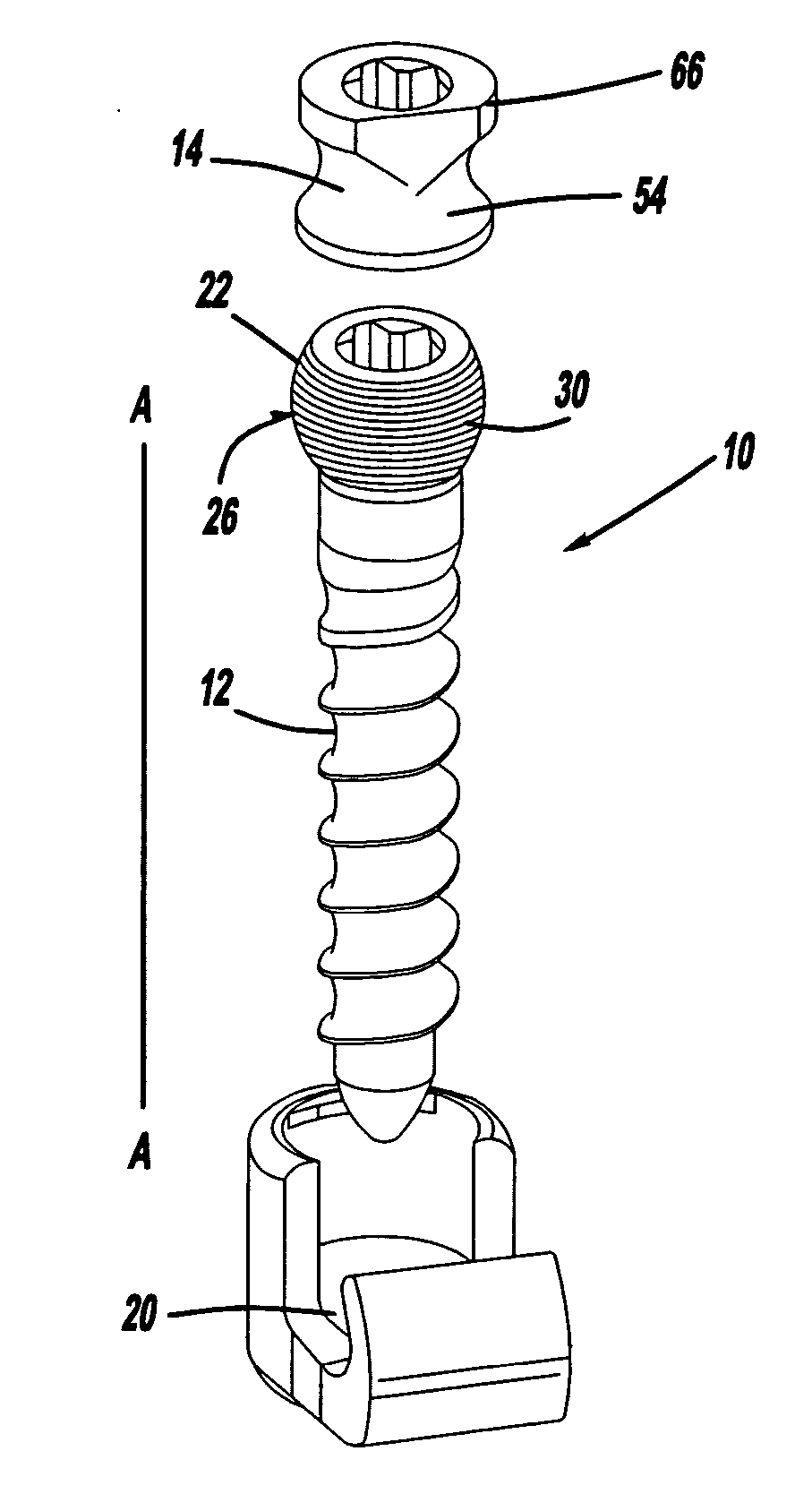
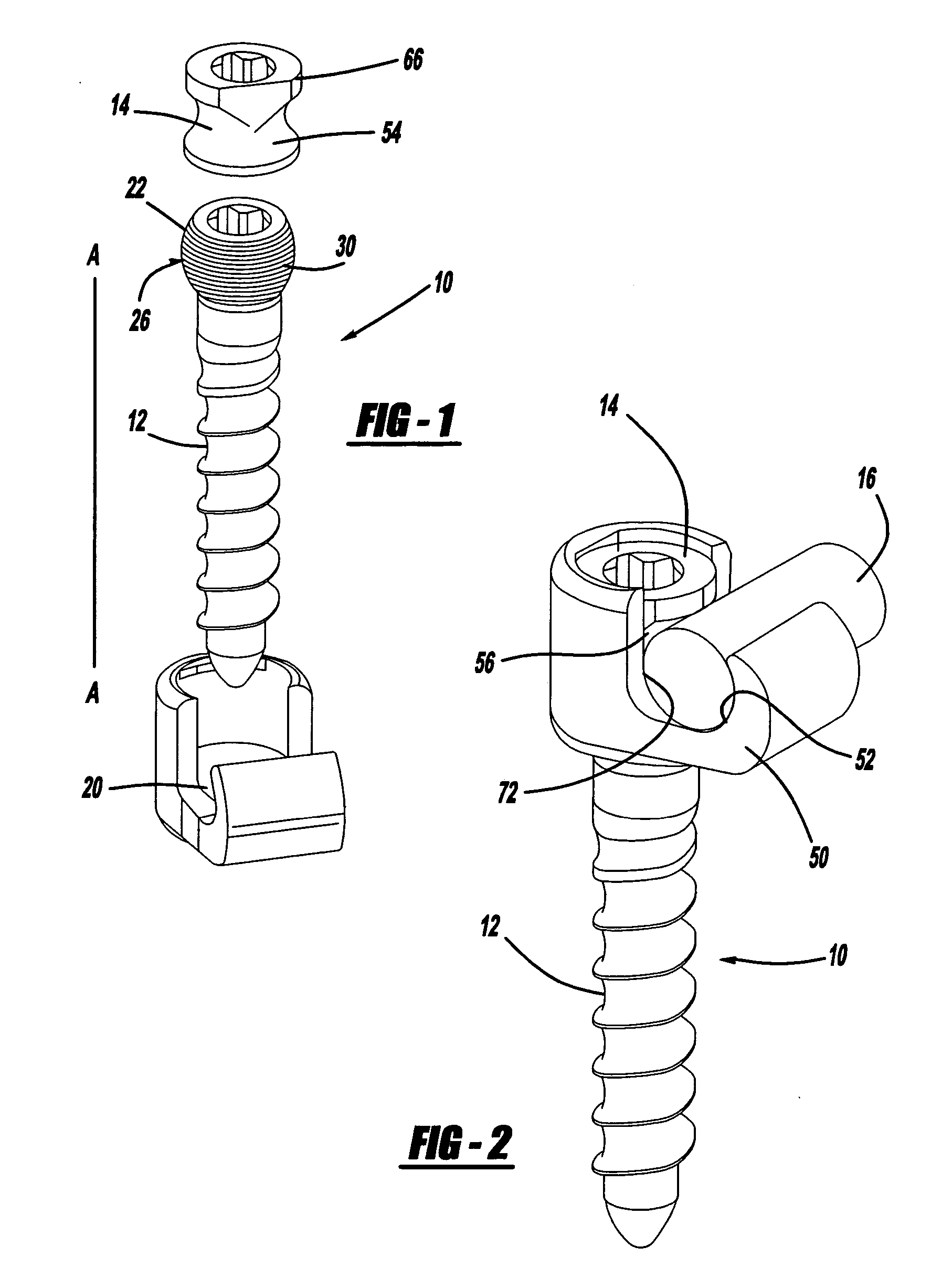
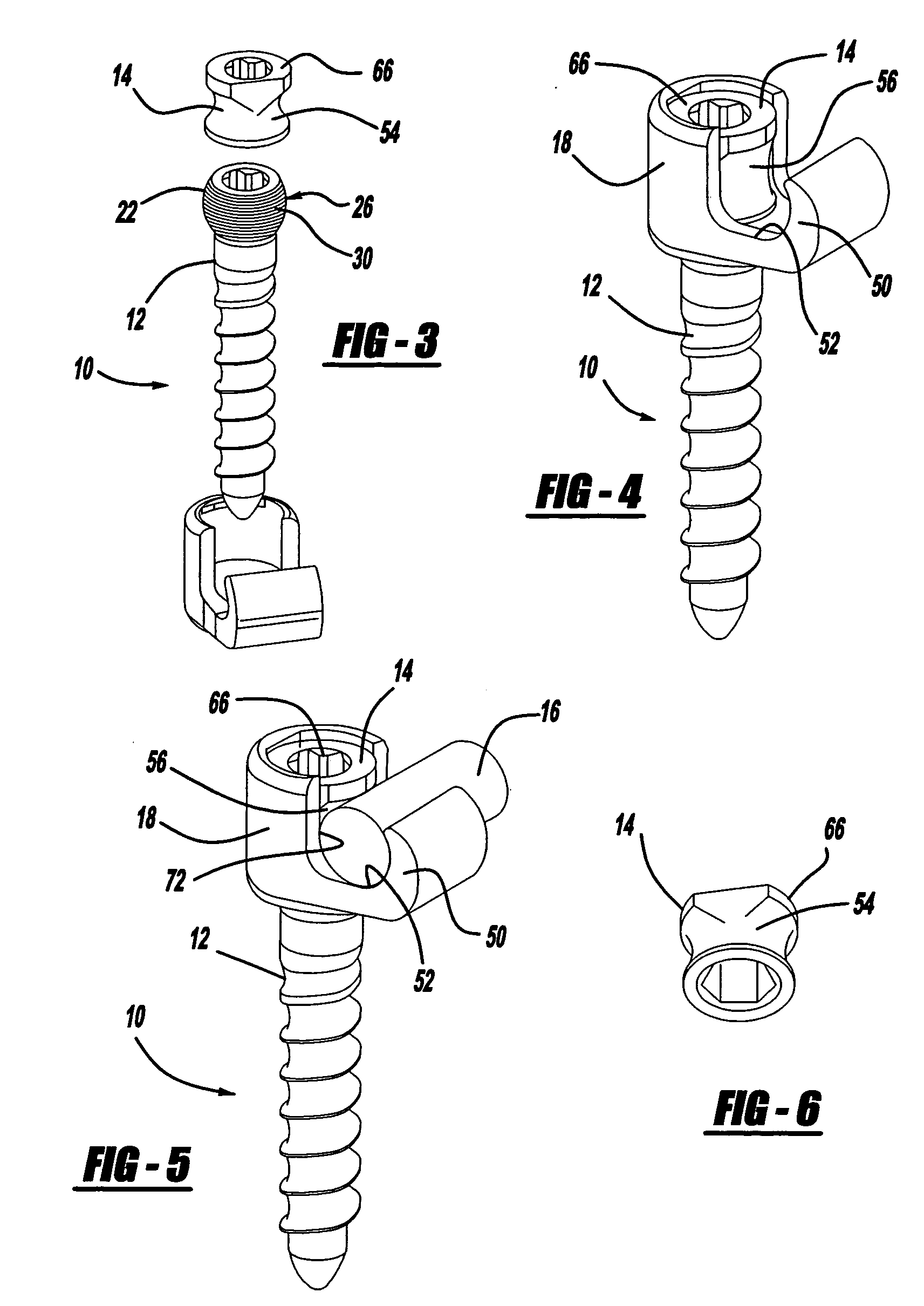
[0041] A screw and rod fixation assembly constructed in accordance with the present invention is generally indicated as 10 in the Figures. Generally, the screw and rod fixation assembly 10 fixes and / or locks together a screw 12 and a rod 16.

[0042] The term “elastic range” as used herein is the limit of stress within which deformation of a body of material completely disappears after the removal of stress, tension, and / or force upon the body of material. Elasticity is the ability of a material to return to its original dimensions after removal of stress, tension, or force placed upon the material. Once the stress, tension, or forces exceed the elastic range however, the material cannot return to its original dimensions and is forever deformed.

[0043] The term “deformation range” as used herein means the excessive amount of strain, force, or load outside the elastic range wherein deformation is maintained and the body of material no longer can return to its original dimensions. Basic...


PUM


Abstract

A screw and rod fixation assembly for fixing a screw and a rod, the assembly having a screw including a screw head, a body portion including a screw head receiving device for receiving the screw head and a rod receiving device for receiving a rod therein, the rod receiving device being offset from the screw head receiving device, and a locking device for locking a rod within the rod receiving device. A medical device for fixing a screw and a rod, the assembly having a screw including a screw head, a body portion having a receiver for receiving the screw head and an offset slot for receiving a rod therein, and a lock for locking the rod within the assembly. A receiving member for receiving and maintaining a rod therein, the receiving member having a body portion having a receiver for receiving a screw head and an offset slot for receiving a rod therein. A rod receiving device having a body portion having a receiver for receiving a screw therein and a rod seat offset within the body portion.

Description

BACKGROUND OF THE INVENTION [0001] 1. Technical Field [0002] The present invention relates to orthopedic devices. More particularly, the present invention relates to screw and rod fixation assemblies for use with bone fixation systems. [0003] 2. Background Art [0004] Several techniques and systems have been developed for correcting and stabilizing the spine and for facilitating fusion at various levels of the spine. Stabilization of the spine for various conditions, including degenerative disk disease, scoliosis, spondylolisthesis, and spinal stenosis, often require attaching implants to the spine and then securing the implants to spinal rods. Such spinal fixation devices can immobilize the vertebrae of the spine and can alter the alignment of the spine over a large number of vertebrae by connecting at least one elongate rod to a sequence of selected vertebrae. The rods can span a large number of vertebrae. The spine anatomy, however, rarely allows for three or more implants to be d...

Claims


Application Information

Patent Timeline
Patent Type & Authority Applications(United States)
IPC IPC(8): A61B17/58A61B17/70
CPCA61B17/7041A61B17/7037
Inventor RICHELSOPH, MARCCLIFT, JOSEPH
Owner RICHELSOPH MARC
Why Eureka
Try Eureka