

Anti-shake apparatus
a technology of anti-shake and apparatus, applied in the field of anti-shake apparatus, can solve problems such as breakag
- Summary
- Abstract
- Description
- Claims
- Application Information
AI Technical Summary
Benefits of technology
Problems solved by technology
Method used
Image

Examples
first embodiment
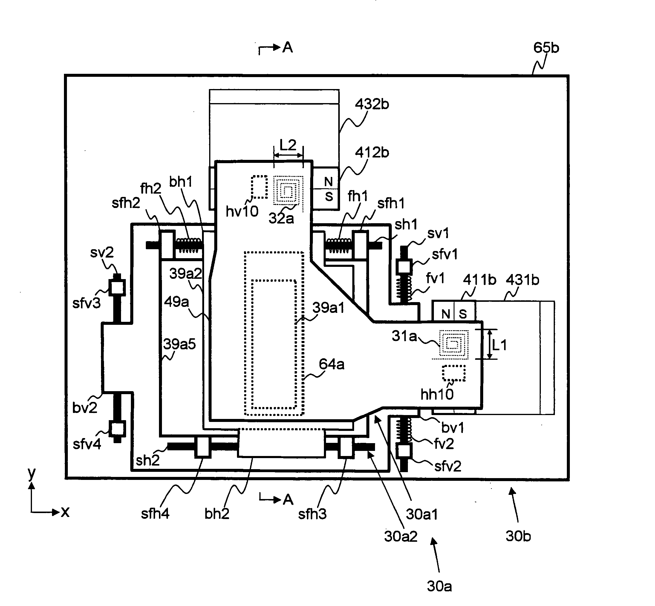
[0100] In the first embodiment, the first and second horizontal urging members fh1 and fh2 and the first and second vertical urging members fv1 and fv2 are connected in series (see FIG. 3). However, the urging members fh1, fh2, fv1, and fv2 may be connected in parallel (not depicted).
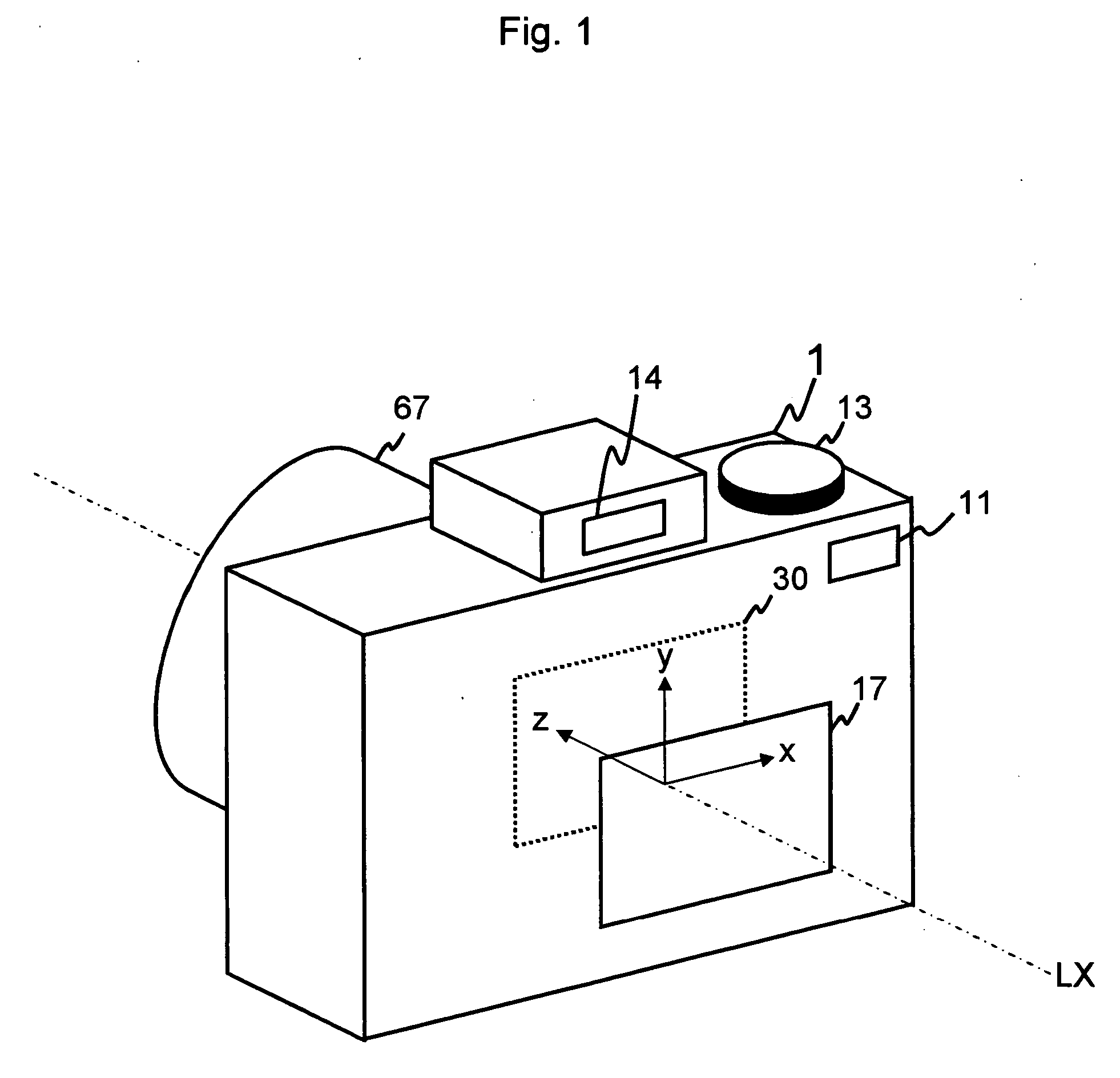
[0101] When the center area of the imaging device 39a1 is located on the optical axis LX of the photographing optical system 67, the location relation between the movable unit 30a and the fixed unit 30b is set up so that the movable unit 30a is located at the center of its movement range in both the first direction x and the second direction y, in order to utilize the full size of the imaging range of the imaging device 39a1 for the anti-shake operation.
[0102] A rectangle shape, which forms the imaging surface (the valid pixel area) of the imaging device 39a1, has two diagonal lines. In the first embodiment, the center of the imaging device 39a1 is the crossing point of these two diagonal lines.
[0103]...
second embodiment
[0182] In the second embodiment, the urging members such as the first and second horizontal urging members fh1 and fh2 and the first and second vertical urging members fv1 and fv2, are arranged on the first and second horizontal shafts sh1 and sh2 and the first and second vertical shafts sv1 and sv2. Accordingly, fixing the movable unit 30a can be further stabilized.
[0183] Next, the third embodiment is explained. In the third embodiment, a function of the CPU 21 in the anti-shake operation, according to time, is different from that of the first embodiment (see FIG. 9).
[0184] Therefore, the third embodiment is explained centering on the constructions (functions) of the photographing apparatus 1 in the third embodiment which are different to the constructions (functions) of the photographing apparatus 1 in the first embodiment.
[0185] The CPU 21 is a control apparatus, which controls each part of the photographing apparatus 1 regarding the imaging operation, and controls each part of...
third embodiment
[0201] In the case where the movable unit 30a is moved by gravity, breakage of the movable unit 30a occurs by the shock of a sudden movement. Further, the image which is indicated on the indicating unit 17 while the movable unit 30a is moving due to gravity, is an image which is imaged where the imaging device is moving and is like a floating image, so that this image is unpleasant for the operator. However, in the third embodiment, such problems do not occur.
[0202] Next, the flow of the anti-shake operation, which is performed at every predetermined time interval (1 ms) as an interruption process in the third embodiment, independently of the other operations, is explained by using the flowchart in FIG. 8. In the third embodiment, after the photographing apparatus 1 is set to the on state, before the 1st interruption of the anti-shake operation is performed, the output signal from the port P21 of the CPU 21 is set to the Lo signal and the value of the first time-count parameter TC1 ...
PUM
 Abstract
Description
Claims
Application Information