Imaging apparatus, method of compensating for hand shake

一种抖动校正、摄像装置的技术,应用在放映装置、洗印装置、静态摄像机等方向,能够解决消耗、多电力等问题,达到抑制电力、最佳抖动校正的效果

Inactive Publication Date: 2008-08-27
CASIO COMPUTER CO LTD
View PDF2 Cites 25 Cited by
  • Summary
  • Abstract
  • Description
  • Claims
  • Application Information

AI Technical Summary

Problems solved by technology

Therefore, more power is consumed for the same level of correction

Method used


Image

  • Imaging apparatus, method of compensating for hand shake
  • Imaging apparatus, method of compensating for hand shake
  • Imaging apparatus, method of compensating for hand shake

Examples


no. 1 Embodiment approach

[0027] First, the appearance of the electronic camera 100 according to the first embodiment of the present invention will be described.

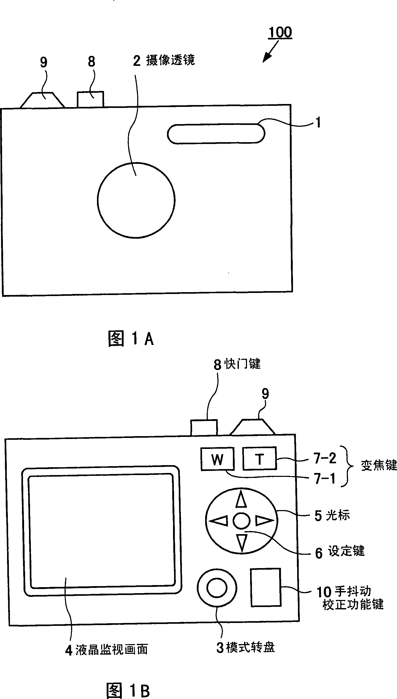
[0028] 1A and 1B are a front view and a rear view showing the appearance of the electronic camera 100 . As shown in FIG. 1A , an electronic camera 100 has a strobe light emitting unit 1 and a photographic lens (lens group) 2 on the front side. As shown in FIG. 1B, the electronic camera 100 is provided with a mode setting dial 3, a liquid crystal display screen 4, a cursor key 5, a setting key 6, a zoom key (W button 7-1, T button 7-2), hand shake keys, Calibration function key 10 etc. In addition, a shutter key 8 and a power button 9 are provided on it, and a USB terminal connection portion is provided on the side not shown in the figure, which is used to connect external devices such as a personal computer or a modem to the electronic camera 100 through a USB cable. occasion.

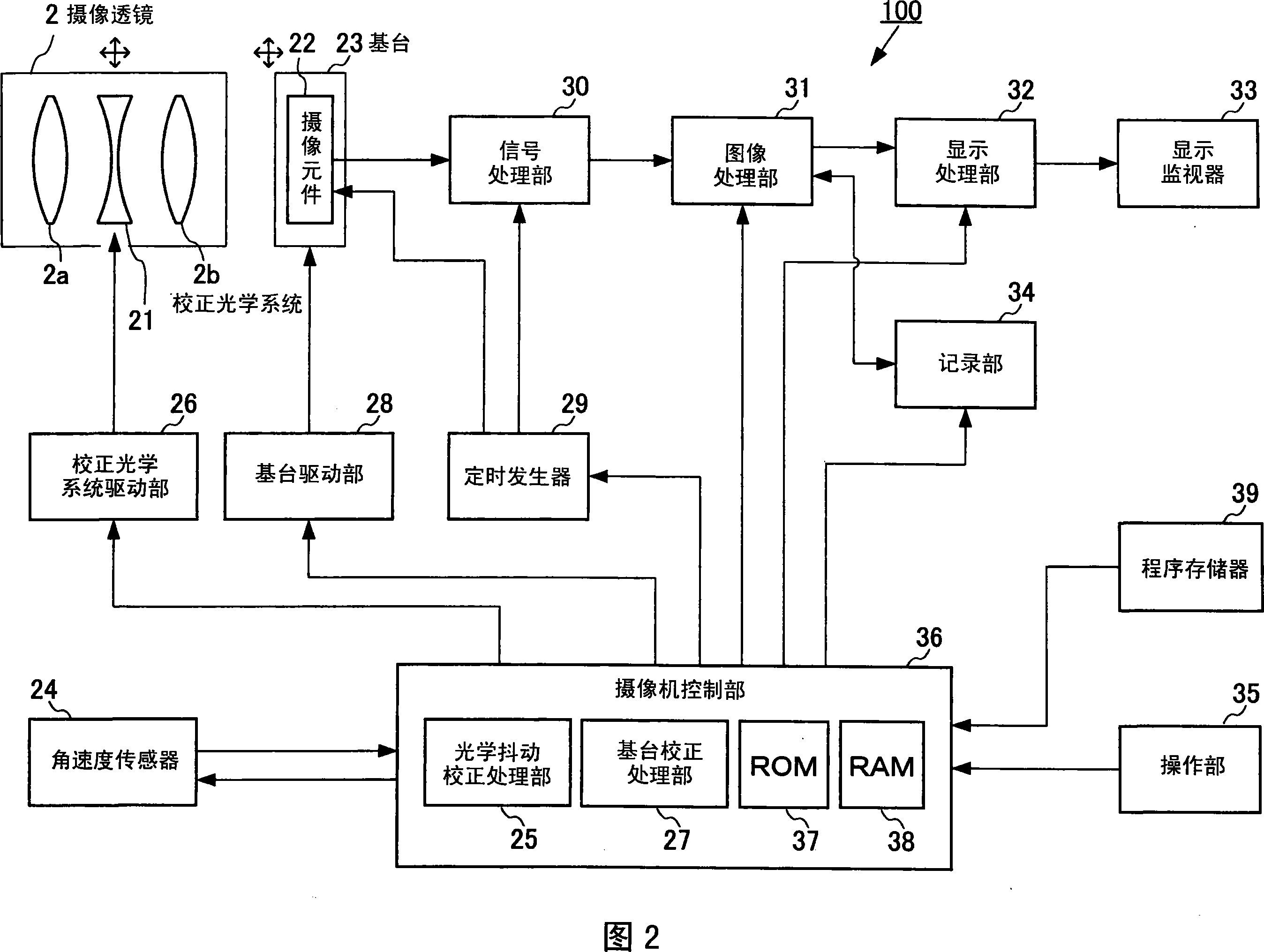
[0029] Next, the structure of the electronic camera 100 havi...

no. 2 Embodiment approach

[0093] Next, the configuration of an electronic camera according to a second embodiment of the present invention will be described.

[0094]This aspect is an embodiment in which the configuration of the electronic camera according to the first embodiment of the present invention is modified. The difference is that it has an electronic hand-shake correction processing unit (not shown) and an electronic vibration correction processing unit (not shown). In addition, the angular velocity sensor 24 shown in FIG. 2 is not used.

[0095] The electronic hand shake correction processing section is provided between the signal processing section 30 and the image processing section 31 shown in FIG. The reading position of the camera moves, so that the captured image data changes.

[0096] Next, details of the electronic hand-shake correction processing unit will be described. The electronic hand-shake correction processing unit includes various units such as a region division unit, a m...

Deformed example 1

[0105] Next, Modification 1 of the first embodiment of the electronic camera of the present invention will be described with reference to the block diagram of the electronic camera shown in FIG. 2 .

[0106] With the structure of the electronic camera shown in FIG. 2 , a gyro sensor is used as the angular velocity sensor 24 . For the gyro sensor, it is preferable to use a vibrating gyro of a chip type, a vibrating gyro, a piezoelectric vibrating gyro sensor, or the like. As shown in FIG. 6A , the gyro sensor detects rotation around the X-axis (pitch), rotation around the Y-axis (yaw), and rotation around the Z-axis (roll).

[0107] FIG. 6B shows the correction of camera shake using the correction optical system 21 and the imaging element 22 in response to the angular velocity of the rotation around the X axis (pitch rotation) and the rotation around the Y axis (yaw) detected by the gyro sensor. direction diagram.

[0108] FIG. 6C is a view showing that the camera rotates aro...


PUM


Abstract

The present invention discloses an imaging apparatus comprising an image pickup lens for shooting an object, an imaging element having an imaging area for picking up an object image focused on the imaging area through the image pickup lens to output an image signal, an angle-rate sensor for detecting a shake amount of the imaging apparatus, an optical shake-compensation unit for moving the image pickup lens in a predetermined direction based on the shake amount detected by the angle-rate sensor to compensate for shake of an object image focused on the imaging area of the imaging element, a base-plate shake compensation unit for moving the imaging element in a predetermined direction based on the shake amount detected by the angle-rate sensor to compensate for shake of the object image focused on the imaging area of the imaging element, and a camera control unit for selectively controlling operation of the optical shake-compensation unit and operation of the base-plate shake compensation unit, thereby compensating for shake of the object image.

Description

[0001] References about the application [0002] This application is based on and claims the priority of the prior Japanese Patent Application No. 2006-291455 filed on October 26, 2006, the entire contents of which include specification, claims, drawings and abstract are hereby incorporated by reference. technical field [0003] The invention relates to an image pickup device and a hand shake correction method using hand shake correction technology. Background technique [0004] In the past, as hand shake correction techniques in electronic cameras, optical correction techniques such as a correction lens movement method, a vertex angle variable prism method, and the like disclosed in Japanese Patent Application No. 2006-33462A are known. In the correction lens movement method, a dedicated correction lens for hand shake correction is provided in the imaging optical system, and is moved by an actuator to cancel out hand shake. In addition, in the variable prism method, an act...

Claims


Application Information

Patent Timeline
Patent Type & Authority Applications(China)
IPC IPC(8): G03B5/00H04N5/225G03B7/30H04N5/232H04N101/00
CPCG03B17/00H04N23/6812H04N23/682
Inventor 神田一彦岛田和典
Owner CASIO COMPUTER CO LTD
Why Eureka
Try Eureka