Method and apparatus for frequency synthesis in direct-conversion transmitters

a transmitter and direct-conversion technology, applied in the field of wireless communication, can solve the problems of high tuning sensitivity voltage control oscillators (vcos) used in such frequency synthesis loops, prone to frequency pulling, and low power

Active Publication Date: 2007-01-25
TELEFON AB LM ERICSSON (PUBL)
View PDF13 Cites 27 Cited by
  • Summary
  • Abstract
  • Description
  • Claims
  • Application Information

AI Technical Summary

Benefits of technology

[0007] According to one embodiment of transmit frequency synthesis as taught herein, a transmitter circuit comprises a first phase-locked loop (PLL) configured to generate a first frequency signal that is non-harmonically related to a transmit frequency signal, a first frequency divider configured to divide the first frequency signal to generate a mixing frequency signal for down converting the transmit frequency signal into an intermediat

Problems solved by technology

While this approach offers economic advantages in terms of circuit simplification and reduced component count, it poses certain design challenges.
However, the relatively low power, high tuning sensitivity Voltage Control Oscillators (VCOs) used in such frequency synthesis loops are prone to frequency pulling, wherein they are disturbed by the modulations of the relatively high-power transmit signal.
Increasing the loop bandwidth of the frequency synthesizer improves its resistance to pulling, but decreases its ability to suppress sideband phase noise.
As such, improving pulling resistance and ACP noise performance represent competing design challenges that are difficult to reconcile in single-loop direct-conv

Method used


Image

  • Method and apparatus for frequency synthesis in direct-conversion transmitters
  • Method and apparatus for frequency synthesis in direct-conversion transmitters
  • Method and apparatus for frequency synthesis in direct-conversion transmitters

Examples


Embodiment Construction

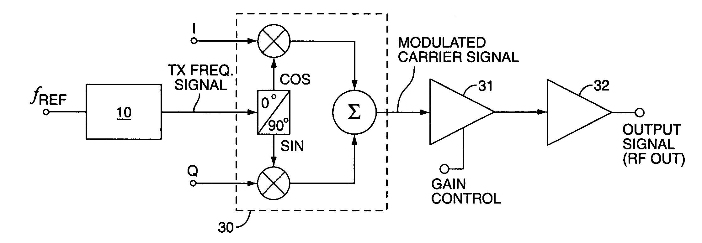
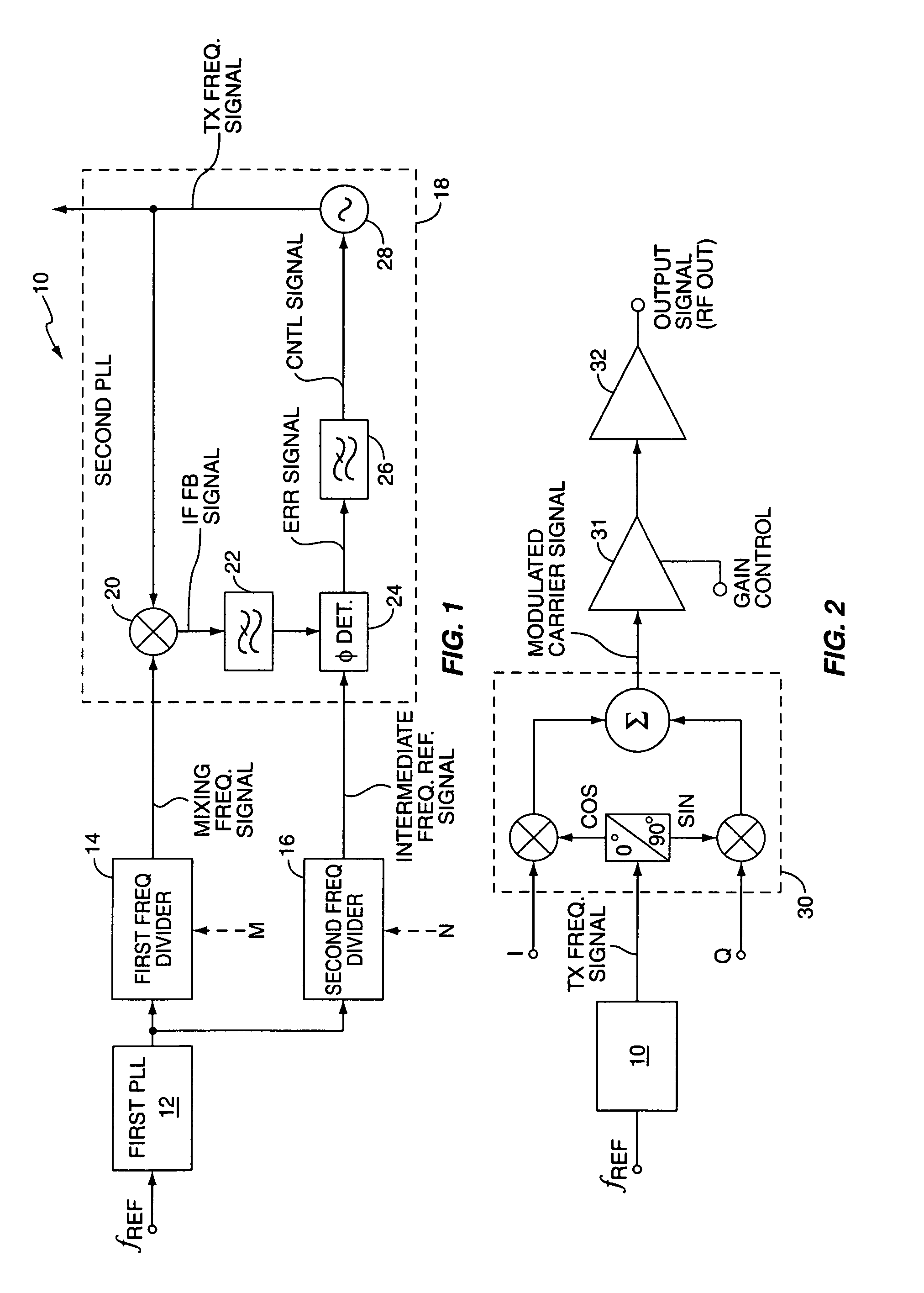
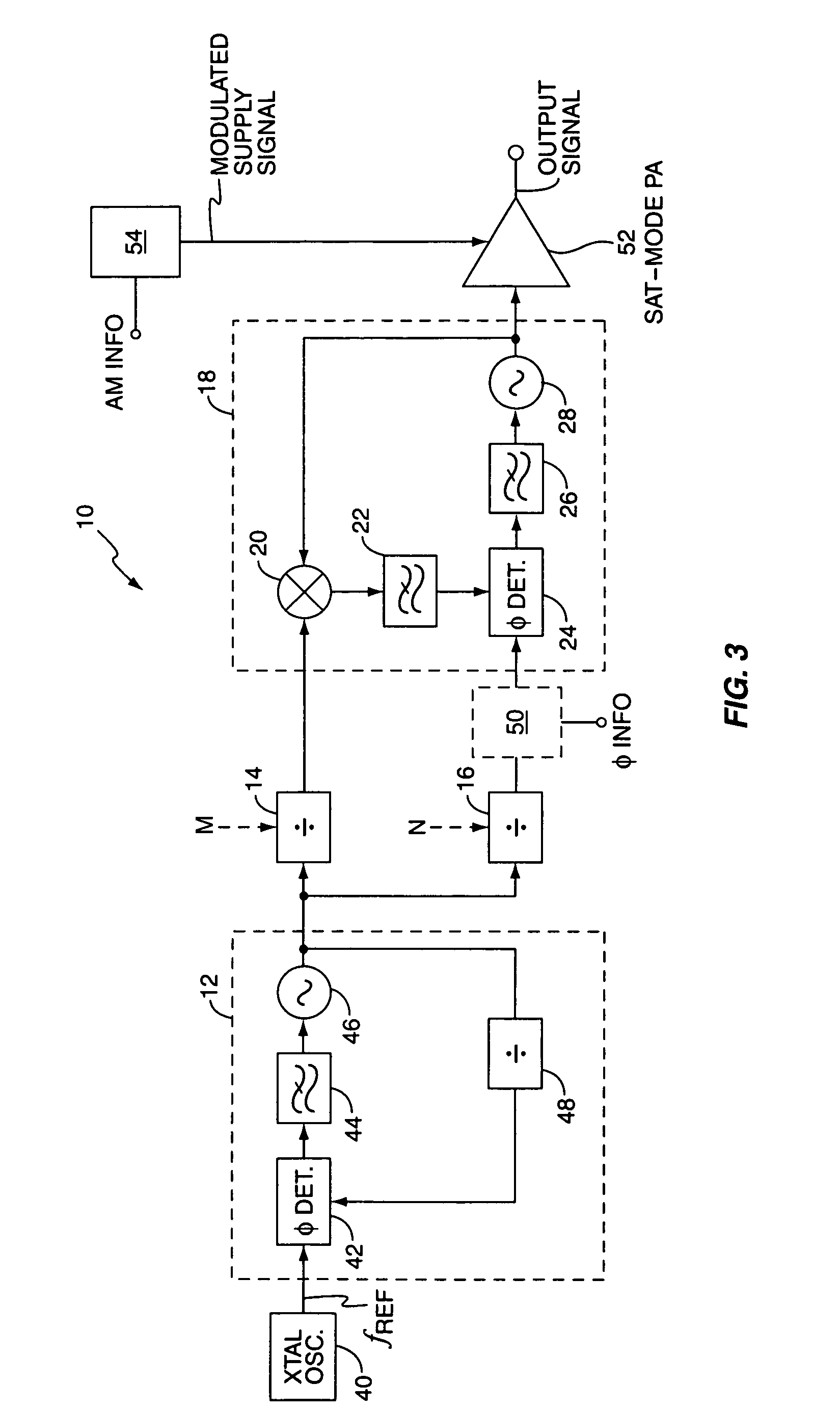
[0019]FIG. 1 illustrates an embodiment of a transmit circuit 10 comprising a first phase-locked loop (PLL) 12, first and second frequency dividers 14 and 16, and a second PLL 18. In the illustrated embodiment, the second PLL 18 is configured as a translational PLL and includes a mixer 20, an optional filter 22, a phase detector 24, a loop filter 26, and a Voltage Controlled Oscillator (VCO) 28.

[0020] The first PLL 12 is configured as a main channel synthesizer, and generates a first frequency signal that is non-harmonically related to the transmit frequency signal output by the second PLL 18. More particularly, the first PLL 12 derives a first frequency signal from a reference frequency signal (fREF). The first frequency divider 14 divides the first frequency signal according to a divisor value “M” to produce a desired mixing frequency signal. The second frequency divider 16 divides the first frequency signal according to a second divisor value “N” to generate an intermediate frequ...


PUM


Abstract

A method and apparatus for direct-conversion transmission generates a first frequency signal that is non-harmonically related to a transmit frequency signal, divides the first frequency signal to obtain a mixing frequency signal, divides the first frequency signal to obtain an intermediate frequency reference signal, generates the transmit frequency signal by using the mixing frequency signal to downconvert the transmit frequency signal into an intermediate frequency feedback signal, and phase-locks the intermediate frequency feedback signal to the intermediate frequency reference signal. The transmit frequency signal may be phase modulated, and may serve as an input to a saturated-mode power amplifier that can be configured for corresponding amplitude modulation. Alternatively, the un-modulated transmit frequency signal serves as the carrier signal input to a quadrature modulator, which imparts I/Q modulations to it, thereby producing a modulated carrier signal for input to a linear power amplifier.

Description

BACKGROUND [0001] The present invention is generally related to wireless communications, and is particularly related to transmit frequency signal generation. [0002] In “direct conversion” transmitters, transmitter modulation and frequency up-conversion generally occur in the same circuit, which means that the transmitted carrier frequency signal is the same as the local oscillator (LO) frequency. While this approach offers economic advantages in terms of circuit simplification and reduced component count, it poses certain design challenges. [0003] For example, the loop bandwidth of the direct-conversion frequency synthesizer generally should be kept relatively narrow in the interest of suppressing sideband phase noise for good Adjacent Channel Power (ACP) suppression performance. However, the relatively low power, high tuning sensitivity Voltage Control Oscillators (VCOs) used in such frequency synthesis loops are prone to frequency pulling, wherein they are disturbed by the modulat...

Claims


Application Information

Patent Timeline
IPC IPC(8): H03L7/00
CPCH03C3/0966H03C3/0983H03C5/00H04B1/30H03L7/1974H03L7/23H03L7/185H03L7/00H04B1/04
Inventor LOMBARDI, FRANK THOMASFREED, JOHN G.ISBERG, MARTIN
Owner TELEFON AB LM ERICSSON (PUBL)
Why Eureka
Try Eureka