
Rotary electrical machine control device

a control device and electric machine technology, applied in the direction of electric generator control, dynamo-electric converter control, dynamo-electric gear control, etc., can solve the problem of consuming an extra amount of regenerated power, and achieve the effect of reducing regenerated power quickly

Active Publication Date: 2014-08-21
AISIN AW CO LTD
View PDF10 Cites 27 Cited by
  • Summary
  • Abstract
  • Description
  • Claims
  • Application Information

AI Technical Summary

Benefits of technology

The present invention relates to a method for reducing regenerated power in a rotary electric machine control system. The invention includes a zero-torque control method for quickly reducing regenerated power when the connection between the rotary electric machine drive device and the DC power source section is blocked. Additionally, a high-loss control method is used to further suppress regenerated power by varying the field current to increase the armature current while maintaining a torque command. The invention also includes a mechanism for setting the torque variation rate at which torque regenerated by the rotary electric machine is reduced to zero based on the rotational speed of the rotary electric machine. Overall, the invention allows for quick and effective reduction of regenerated power to prevent damage or vibration.

Problems solved by technology

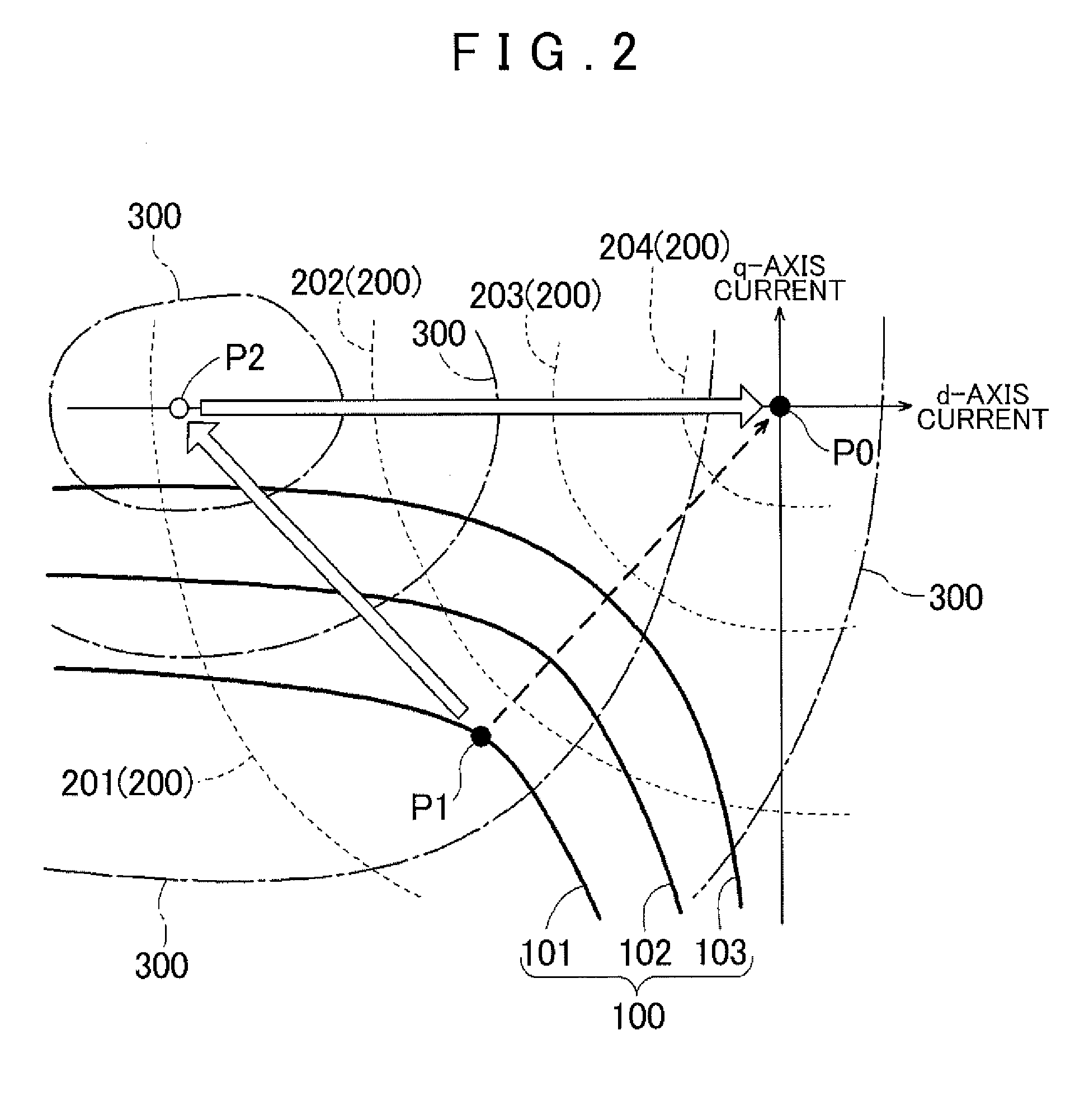
In addition, it is possible to further suppress regenerated power by executing the high-loss control in which the field current is varied so as to increase the armature current while maintaining a torque command provided in the zero-torque control, thereby consuming an extra amount of regenerated power.

Method used


Image

  • Rotary electrical machine control device
  • Rotary electrical machine control device
  • Rotary electrical machine control device

Examples


Embodiment Construction

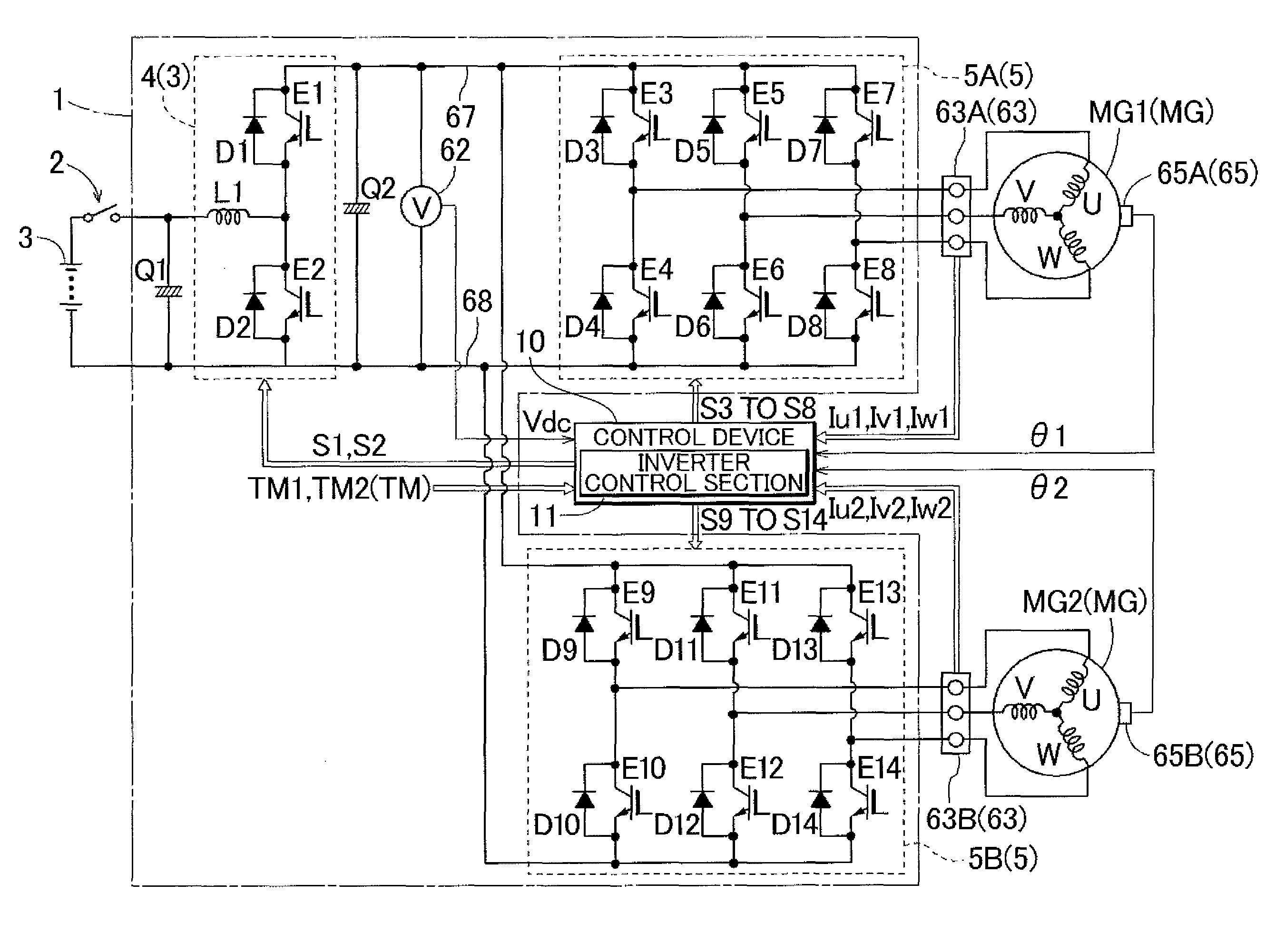
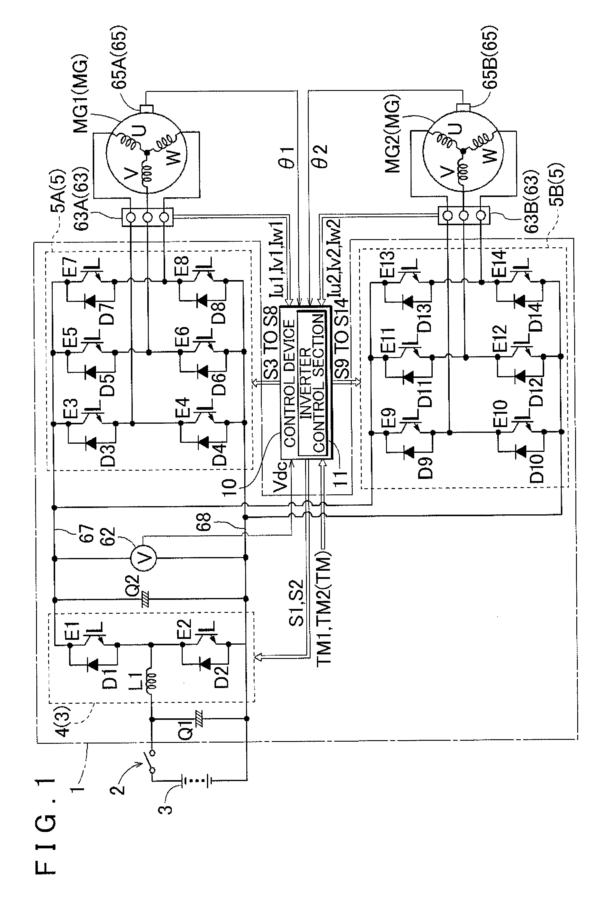
[0020]An embodiment of the present invention will be described with reference to the drawings using a case where the present invention is applied to a rotary electric machine control device that controls a drive device (rotary electric machine drive device) for a hybrid vehicle of a so-called 2-motor split type as an example. The hybrid vehicle includes an internal combustion engine (not shown) and a pair of motors (rotary electric machines) MG1 and MG2 each serving as a drive power source. The drive device for the hybrid vehicle includes a differential gear device (not shown) for power distribution that distributes output of the internal combustion engine to the side of the first motor MG1 and the side of wheels and the second motor MG2. In the embodiment, a drive device 1 (rotary electric machine drive device) is formed as a device that drives the two motors MG1 and MG2. Here, each of the first motor MG1 and the second motor MG2 is an AC motor that operates on multi-phase AC (here...


PUM


Abstract

Regenerated power fed from a rotary electric machine is immediately reduced where connection between an electric machine and a DC power source is blocked. An inverter control section controls the inverter by controlling an armature current in a two-axis orthogonal coordinate system that rotates in synchronization with the rotary electric machine, the armature current being a vector obtained by synthesizing a field current and a drive current extending along respective axes of the orthogonal coordinate system. If it is determined that connection between the DC power source section and the inverter is in a blocked state, the inverter control section executes zero-torque control in which the inverter is controlled such that torque regenerated by the rotary electric machine becomes zero, and executes high-loss control in which the field current is varied so as to increase the armature current while maintaining a torque command provided in the zero-torque control.

Description

INCORPORATION BY REFERENCE[0001]The disclosure of Japanese Patent Application No. 2011-143292 filed on Jun. 28, 2011 including the specification, drawings and abstract is incorporated herein by reference in its entirety.BACKGROUND OF THE INVENTION[0002]The present invention relates to a rotary electric machine control device that controls a rotary electric machine drive device including an inverter interposed between a DC power source section including a power storage device and an AC rotary electric machine to perform power conversion between DC power from the DC power source section and AC power for the rotary electric machine.DESCRIPTION OF THE RELATED ART[0003]In order to reduce a load on the environment due to consumption of fossil fuel, there have been proposed electric vehicles driven by an AC rotary electric machine and hybrid vehicles driven by an AC rotary electric machine and an internal combustion engine. In the electric vehicles and the hybrid vehicles, the rotary elect...

Claims


Application Information

Patent Timeline
IPC IPC(8): H02P21/00B60L3/00B60K6/445B60L9/18B60L50/16H02P21/12H02P21/22H02P21/36H02P27/04H02P27/08
CPCH02P21/0092H02P3/18B60L3/003B60L3/0046B60L3/0061H02P21/36Y02T10/64
Inventor SEKIYA, TAKAOMISAHA, SUBRATANAKAMURA, MITSURUSHIMADA, ARINORI
Owner AISIN AW CO LTD
Learn More