Control device for continuously variable transmission

a technology of control device and transmission, which is applied in the direction of gearing control, belt/chain/gearing, gearing element, etc., can solve the problems of difficult re-starting of the vehicle after stopping the vehicle, and extremely difficult to apply the conventional fail-safe function to the transmission, so as to reduce the line pressure and ensure the minimum vehicle performance. , the effect of reducing the line pressur

Active Publication Date: 2007-10-04
SUBARU CORP
View PDF4 Cites 25 Cited by
  • Summary
  • Abstract
  • Description
  • Claims
  • Application Information

AI Technical Summary

Benefits of technology

[0010]It is an object of the invention to secure the minimum driving performance as well as safety during driving even when the line pressure control valve and the speed ratio control valve attain a failed state in a continuously variable transmission including a pulley having a plurality of hydraulic fluid chambers.
[0012]In the control device for a continuously variable transmission according to the invention, the first reducing valve is provided between the line pressure control valve and the first variable speed pressure chamber and reduces the line pressure supplied to the first variable speed pressure chamber.
[0013]In the control device for a continuously variable transmission according to the invention, the second reducing valve is provided between the speed ratio control valve and the second variable speed pressure chamber and reduces the variable speed control pressure supplied to the second variable speed chamber.
[0018]According to the invention, there are provided the first reducing valve that reduces the line pressure when the line pressure exceeds the first limit pressure and the second reducing valve that reduces the variable speed control pressure when the variable speed control pressure exceeds the second limit pressure. Therefore, if the line pressure control valve and the variable speed control valve fail, the speed ratio can be controlled at a prescribed target speed ratio. In this way, abrupt down-shifting can be prevented and the safety as well as the minimum vehicle performance can be secured.

Problems solved by technology

When the speed ratio control valve attains a failed state and the speed ratio is controlled to the overdrive side, it is difficult to re-start the vehicle after stopping the vehicle.
However, it has been extremely difficult to apply the conventional fail-safe function to the transmissions.

Method used


Image

  • Control device for continuously variable transmission
  • Control device for continuously variable transmission
  • Control device for continuously variable transmission

Examples


Embodiment Construction

[0026]Now, an embodiment of the invention will be described in detail in conjunction with the accompanying drawings.

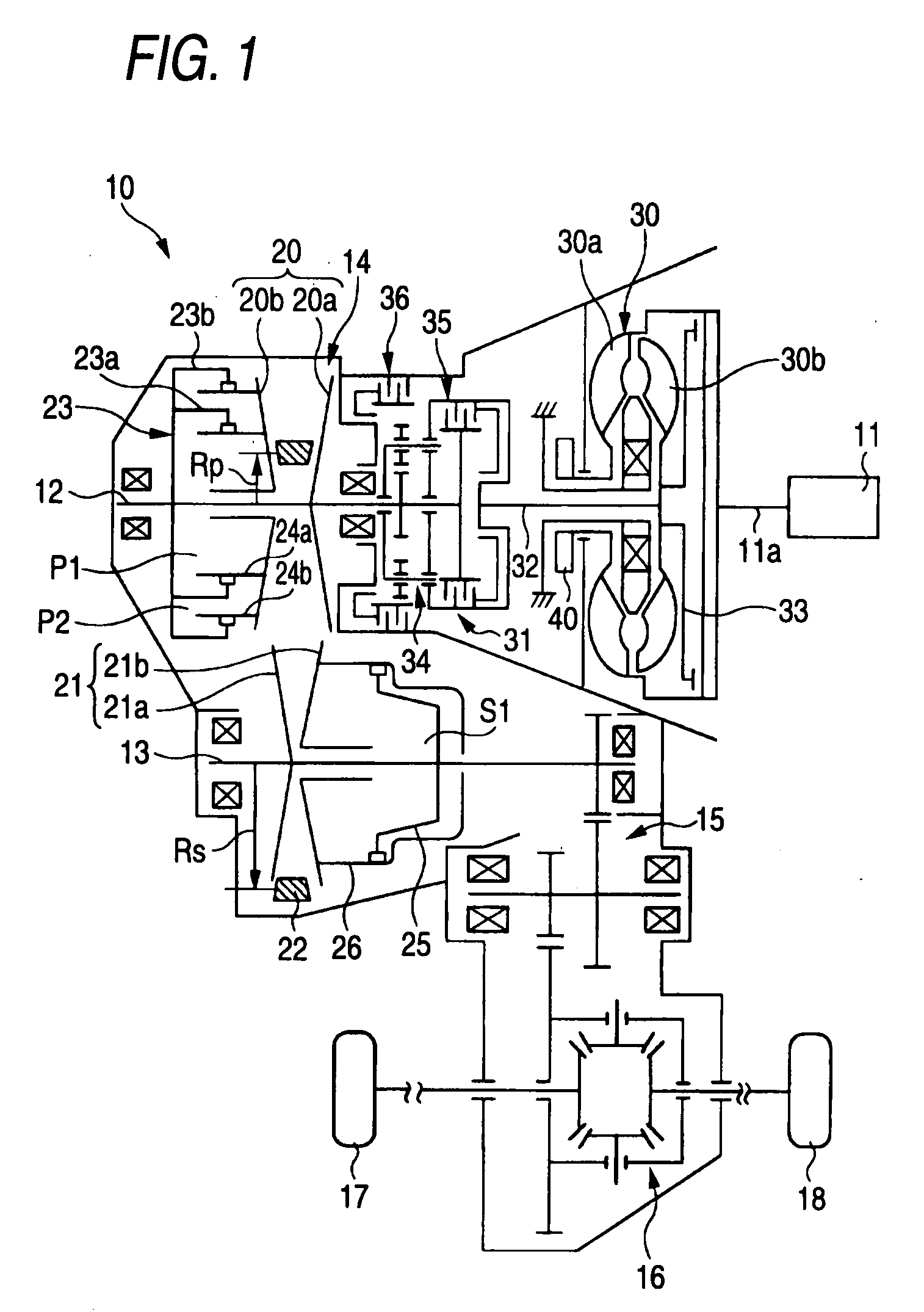
[0027]FIG. 1 is a skeleton view of a continuously variable transmission 10 that is controlled by a control device according to the embodiment of the invention. As shown in FIG. 1, the continuously variable transmission 10 is a belt-driving type continuously variable transmission and has a primary shaft 12 driven by an engine 11 and a secondary shaft 13 parallel to the primary shaft. A transmission mechanism 14 is provided between the primary shaft 12 and the secondary shaft 13, the rotation of the primary shaft 12 is transmitted to the secondary shaft 13 through the transmission mechanism 14, and the rotation of the secondary shaft 13 is transmitted to the left and right driving wheels 17 and 18 through a reduction mechanism 15 and a differential mechanism 16.

[0028]A primary pulley 20 as a variable speed pulley is provided at the primary shaft 12, and the primary pulle...


PUM


Abstract

Safety as well as the minimum driving performance is secured by preventing abrupt down-shifting if a line pressure valve or a primary pressure control valve fails. A line pressure path connected to an oil pump is connected with a line pressure control valve. A first primary pressure path branched from the line pressure path is connected with a hydraulic fluid chamber through a fail-safe valve, and a secondary pressure path branched from the line pressure path is connected to a hydraulic fluid chamber. The line pressure control valve is connected with a second primary pressure path in communication with a hydraulic fluid chamber, and this secondary primary pressure path is provided with a primary pressure control valve and a limiter valve. When the line pressure control valve and the primary pressure control valve fail and excess line pressure or primary pressure is output, the pressure in the hydraulic fluid chamber is reduced by the fail-safe valve, so that the pressure in the hydraulic fluid chamber is reduced by the limiter valve.

Description

CROSS REFERENCE TO RELATED APPLICATIONS[0001]The disclosure of Japanese Application No. 2006-090311 filed on Mar. 29, 2006 including the specification, drawings, and abstract is incorporated herein by reference in its entirety.BACKGROUND OF THE INVENTION[0002]1. Field of the Invention[0003]The present invention relates to a control device for a continuously variable transmission for use in a vehicle.[0004]2. Description of the Related Art[0005]The continuously variable transmission (CVT) for use in a vehicle includes a primary pulley provided at an input shaft and a secondary pulley provided at an output shaft and controls its speed ratio by changing the winding diameter of a driving belt or the like placed around these pulleys. The primary and secondary pulleys each include a fixed sheave and a movable sheave opposing the fixed sheave. The movable sheave is moved in the axial direction, which allows the pulley groove width to be changed, so that the winding diameter of the driving ...

Claims


Application Information

Patent Timeline
Patent Type & Authority Applications(United States)
IPC IPC(8): F16H61/00F16H59/00F16H59/68F16H59/70F16H61/12F16H61/66F16H61/662
CPCF16H61/12F16H61/66272F16H61/66259
Inventor NISHIDA, MASAYUKI
Owner SUBARU CORP
Why Eureka
Try Eureka