Gripping apparatus, robot system and gripping method

a robot system and gripping technology, applied in the field of gripping apparatus, can solve the problems of inability to precisely position the gripping object, the tip of the tool cannot be precisely positioned with respect to the workpiece, etc., and achieve the effect of improving the reproduction precision of the positioning of the tool, improving the precision of the reproduction of the positioning of the gripping object, and ensuring the operation

Active Publication Date: 2012-01-12
CANON KK
View PDF9 Cites 27 Cited by
  • Summary
  • Abstract
  • Description
  • Claims
  • Application Information

AI Technical Summary

Benefits of technology

[0011]According to the present invention, the gripping apparatus has the palm side contact surface brought into contact with the gripping object side contact surface, and the holes are configured to determine the position of the gripping object in the tangential direction of the palm side contact surface and the position of the gripping object in the rotational direction around the normal line of the palm side contact surface which is the rotary shaft center. Therefore, a reproduction precision of the positioning of the gripping object can be improved, and the gripping object can precisely be positioned.
[0012]Moreover, according to the robot system of the present invention, the reproduction precision of the positioning of the tool can be improved, and the tool can precisely be positioned. In consequence, the robot can securely perform an operation by use of the tool.
[0013]Furthermore, according to the gripping method of the present invention, after attaching the projections of the gripping object onto the reference surfaces of the holes of the palm, the gripping object side contact surface of the gripping object is pressed onto the palm side contact surface of the palm. In consequence, the reproduction precision of the positioning of the gripping object improves, and the gripping object is precisely positioned.

Problems solved by technology

However, in the above conventional gripping apparatus, the posture of the gripping object can be regulated, but a direction of the gripping object along the guide groove is not regulated, whereby it is not possible to precisely position the gripping object.
Therefore, the tip of the tool cannot precisely be positioned with respect to the workpiece.

Method used


Image

  • Gripping apparatus, robot system and gripping method
  • Gripping apparatus, robot system and gripping method
  • Gripping apparatus, robot system and gripping method

Examples


first embodiment

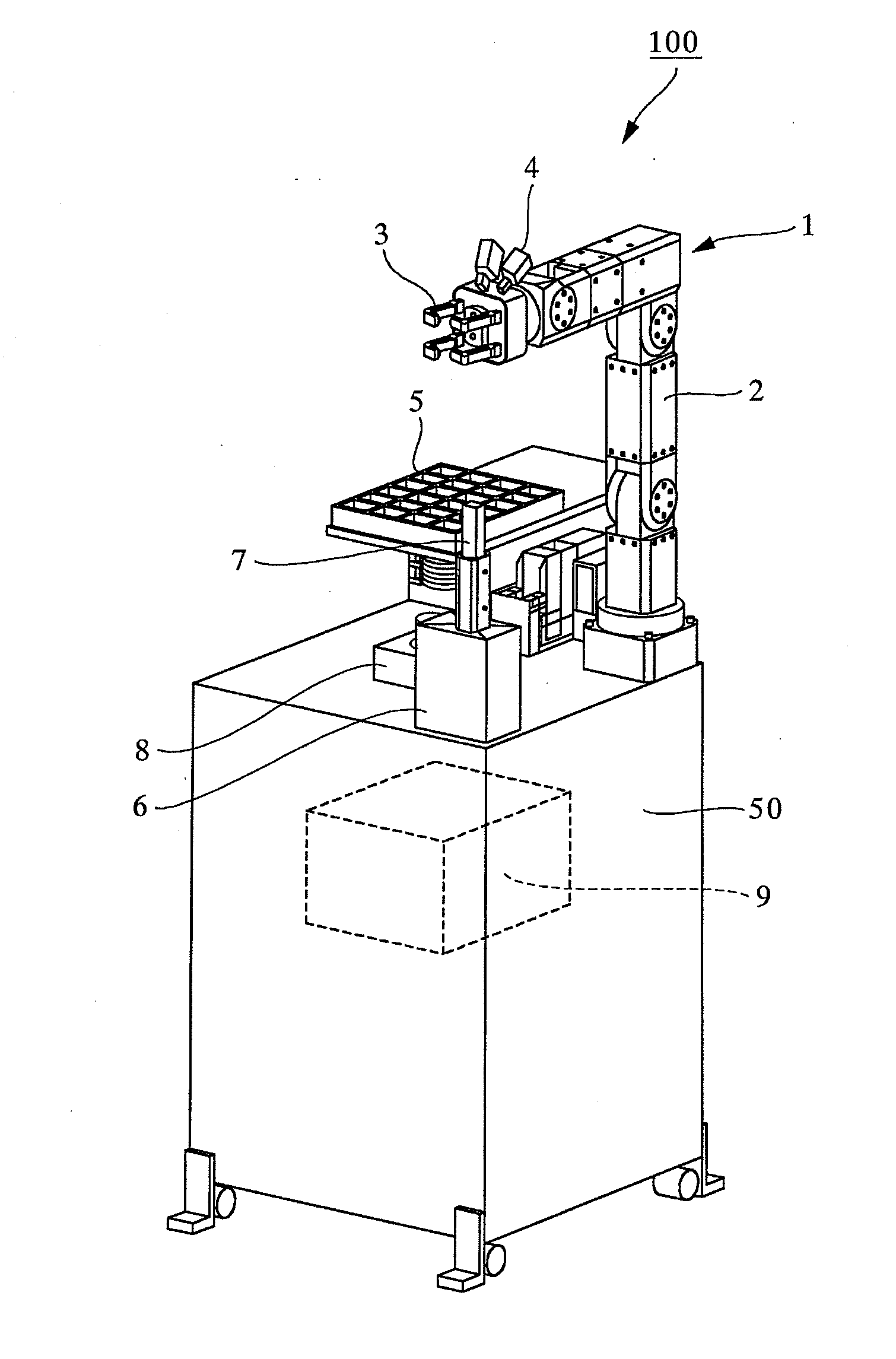
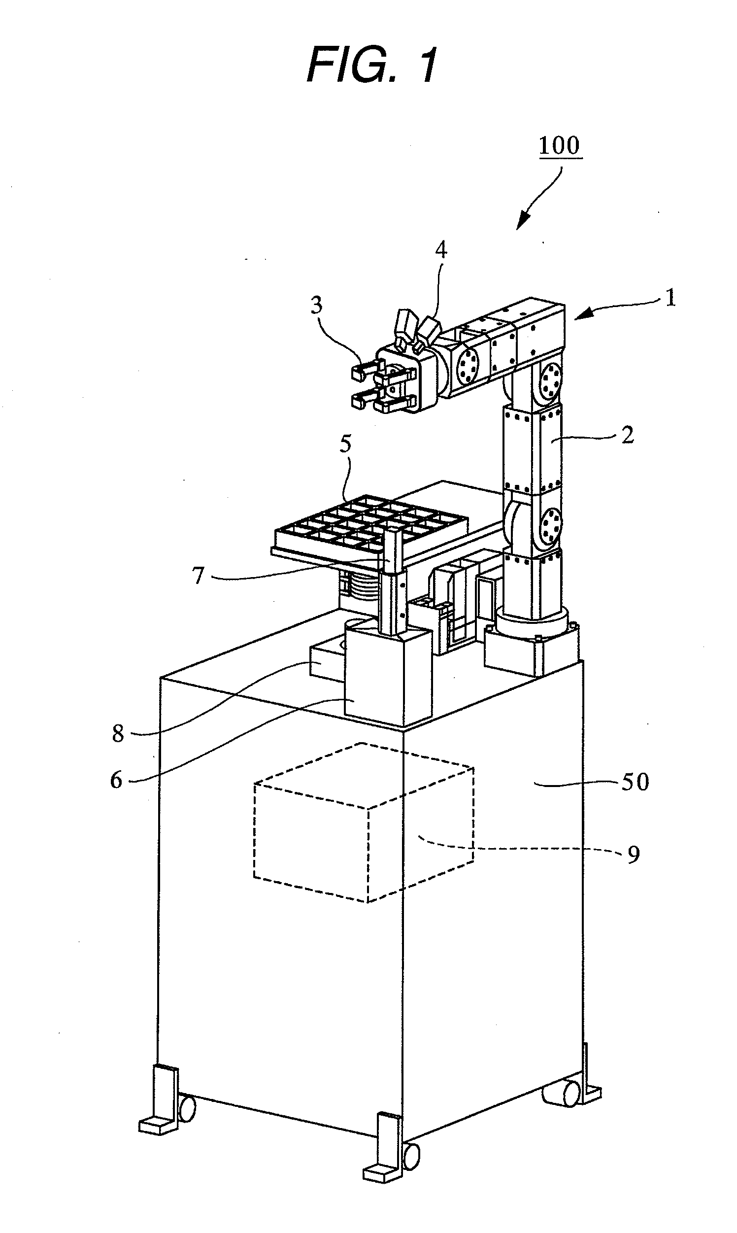
[0032]FIG. 1 is a perspective view illustrating a robot system according to a first embodiment of the present invention. As shown in FIG. 1, a robot system 100 includes a robot 1, a base 50 to which the robot 1 is fixed and which is a working area of the robot 1, and a tool 7 which is a gripping object. The robot system 100 is an assembling system in which the robot 1 performs an assembling operation by use of the tool 7. The robot 1 includes an articular arm 2 having six shafts, and a multifingered hand 3 which is a gripping apparatus provided at the tip of the arm 2 via a kinesthetic sensor (not shown). Moreover, to the tip of the arm 2, a small-sized camera 4 is attached. The base 50 is provided with a part supplier 5 for supplying parts to be assembled, and a tool table 6 on which the tool 7 for fastening small screws is disposed. Moreover, in the center of the base 50, a gripping jig 8 for use in assembling workpieces is provided. Above the base 50, there is disposed a camera (...

second embodiment

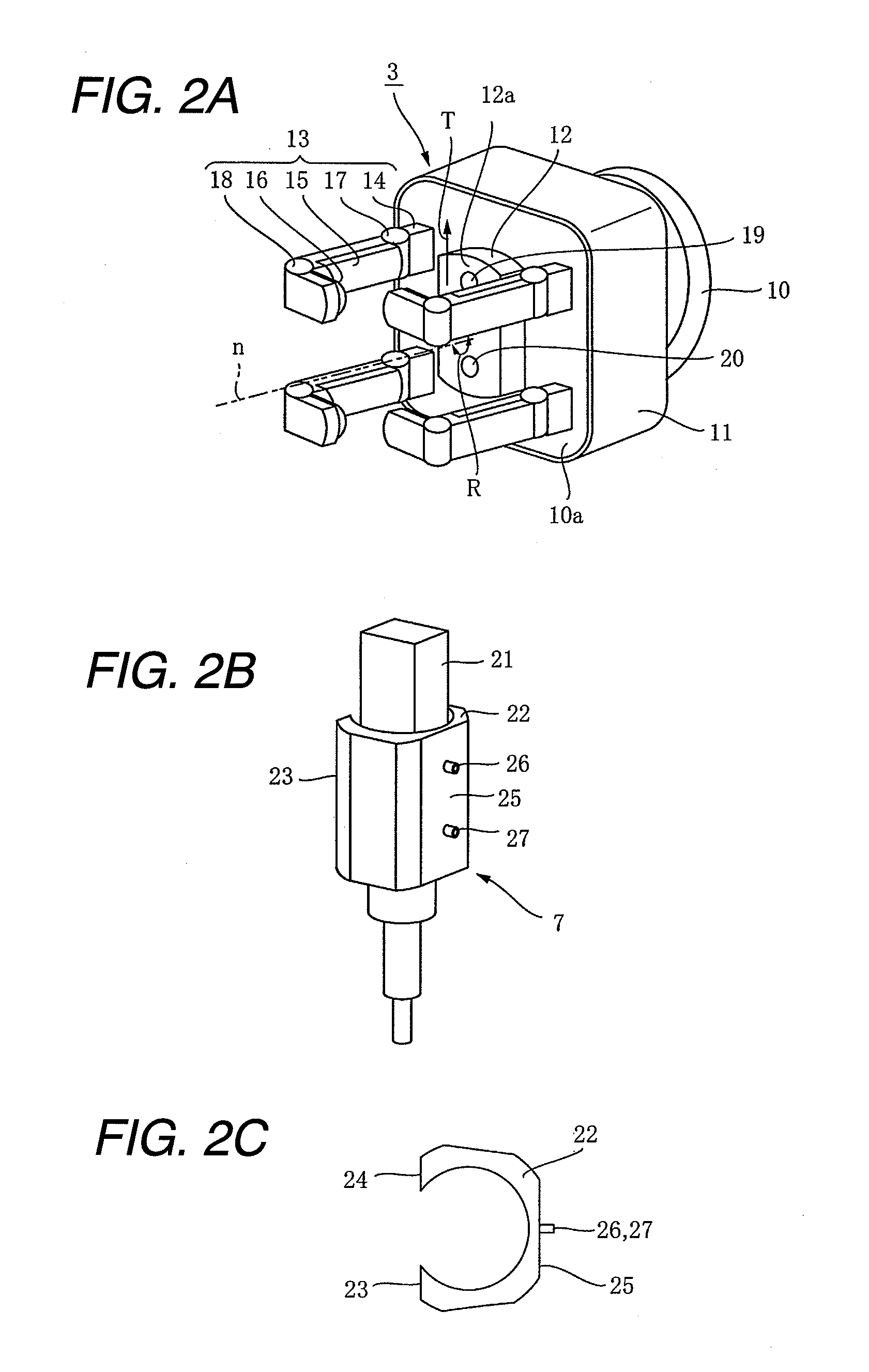
[0046]Next, a robot system including a robot having a gripping apparatus according to a second embodiment of the present invention will be described. FIG. 3A and FIG. 3B are explanatory views illustrating a main part of the robot system according to the second embodiment of the present invention. FIG. 3A is an exemplary diagram of a palm side contact surface of a palm of the gripping apparatus, and FIG. 3B is an exemplary diagram of a gripping object side contact surface of an attachment member of a tool. It is to be noted that the whole constitution of the robot system is similar to the first embodiment, and is different from the first embodiment in a shape of a hole formed in the palm side contact surface of the palm.

[0047]As shown in FIG. 3A, a contact surface 12a of a palm 12 is provided with two holes 19 and 20, and as shown in FIG. 3B, a contact surface 25 of an attachment member 22 of a tool 7 is provided with two projections 26 and 27.

[0048]As shown in FIG. 3A, on a side wal...


PUM


Abstract

In a conventional technology, it has been difficult to precisely position a gripping object when gripping the gripping object. Therefore, in the present invention, a multifingered hand includes a palm and a plurality of fingers having joints, to grip a tool with the palm and the plurality of fingers. The palm has a palm side contact surface brought into contact with a gripping object side contact surface of the tool. The palm side contact surface is provided with holes into which projections provided on the gripping object side contact surface are inserted. Moreover, when the projections are inserted into the holes, the tool is positioned in a tangential direction of the palm side contact surface, and the tool is also positioned in a rotational direction around a normal line of the palm side contact surface which is a rotary shaft center.

Description

BACKGROUND OF THE INVENTION[0001]1. Field of the Invention[0002]The present invention relates to a gripping apparatus mounted on an arm of a robot, a robot system including a robot having a gripping apparatus, and a gripping method in which a gripping apparatus grips a gripping object.[0003]2. Description of the Related Art[0004]Heretofore, a robot system including a robot having a gripping apparatus has been known. In recent years, there has been demanded a robot system which realizes a manual assembling operation by a robot. Moreover, in the manual assembling operation, conveyors are removed, and a person cell production system is introduced in which persons directly convey workpieces, but for the purpose of replacing person cells with robot cells, a robot system is demanded which grips various parts to perform the assembling operation. Moreover, a robot system is demanded in which a robot performs an assembling operation by use of an assembling tool and an assembling jig such as ...

Claims


Application Information

Patent Timeline
Patent Type & Authority Applications(United States)
IPC IPC(8): B25J15/08
CPCB25J15/0009
Inventor NAKASUGI, MIKIOMIYAZAKI, YOSHIYUKIYOKOI, AKIYOSHI
Owner CANON KK
Why Eureka
Try Eureka