Electrophotographic photosensitive member, process cartridge and electrophotographic apparatus

a photosensitive member and electrophotography technology, applied in the field of electrophotography photosensitive member and process cartridge, can solve the problems of degrading the characteristics of the electrophotographic photosensitive member, affecting the cleaning performance of the surface, etc., to achieve excellent surface smoothness, suppress blade chattering and blade turn-up, and improve cleaning performance

Active Publication Date: 2010-01-12
CANON KK
View PDF30 Cites 57 Cited by
  • Summary
  • Abstract
  • Description
  • Claims
  • Application Information

AI Technical Summary

Benefits of technology

[0013]Conversely, in the case where lubricity is imparted to the surface of a photosensitive member by applying a fluorine- or silicon-containing compound serving as a lubricant instead of roughening the surface, since the properties of the fluorine- or silicon-containing compound can be exhibited in the beginning, a high degree of smoothness can be obtained and cleaning-blade chattering and cleaning-blade turn-up can be suppressed. As a result, good cleaning performance may be often obtained. However, when the surface layer is abraded during long-term repeated use and accordingly a large amount of fluorine- or silicon-containing compound present is removed from the proximity of the surface, a sufficient effect cannot be obtained. For this reason, the use of such a compound may not be sufficient to persistently obtain persistently high effects during long-term repeated use. To prevent blade chattering and blade turn-up on the part of an electrophotographic photosensitive member, a large amount of fluorine- or silicon-containing compound must be added to the member. In this case, mechanical strength of the photosensitive member tends to decrease, so that the photosensitive member has insufficient durability. On the other hand, when silicone oil such as dimethylsilicone oil is added in an amount sufficient to obtain desired lubricity, residual potential tends to significantly increase and the coating constituting a charge transport layer tends to turn white and turbid. Also from the aspect of the optical characteristics of the coating, troubles may arise: image quality deteriorates; and images with a lower density due to the decrease in sensitivity and memory images are formed.
[0015]In view of the aforementioned circumstances, an object of the present invention is to provide an electrophotographic photosensitive member, which maintains excellent smoothness of the surface thereof and exhibits improved cleaning performance during long-term repeated use, and which suppresses cleaning-blade chattering and turn-up, thereby providing good image reproduction, as well as to provide a process cartridge and electrophotographic apparatus having the electrophotographic photosensitive member.
[0016]The present inventors have conducted intensive studies. As a result, they found the aforementioned problem is effectively achieved and a remarkable effect can be exerted for long time during repeated use by adding a silicon- or fluorine-containing compound to a surface layer of an electrophotographic photosensitive member and forming depressed portions of a predetermined shape on the surface layer. Based on the finding, they have arrived at the present invention.
[0021]The present invention can provide an electrophotographic photosensitive member, which maintains excellent smoothness of the surface thereof and exhibits improved cleaning performance during long-term repeated use, and which suppresses blade chattering and blade turn-up, thereby providing good image reproduction, as well as provides a process cartridge and electrophotographic apparatus having the electrophotographic photosensitive member.

Problems solved by technology

However, the method of dispersing fine particles in the surface layer of an electrophotographic photosensitive member described in Patent Document 1 has problems below: the surface of the photosensitive member is scratched by the dispersion: a large amount of fine particles must be added in order for dispersed fine particles to produce long-lasting effect upon cleaning performance; and a dispersion agent or an auxiliary dispersion agent may degrade characteristics of an electrophotographic photosensitive member, such as potential characteristic, during long-term repeated use.
Furthermore, in the surface of an electrophotographic photosensitive member described in each of Patent Documents 2 to 6, when an about several-μm area of the surface-processed region in the surface which is roughened is observed, the micro region is found to be not uniform.
Additionally, in a method of roughening the surface of an electrophotographic photosensitive member by a film-shaped polishing sheet or blast, even though a fluorine- or silicon-containing compound is present in the surface, the fluorine- or silicon-containing compound distributed in the surface is ripped off or the compound fails to uniformly distribute by an inherent feature of the compound, that is, migration toward a front surface.
As a result, the method is not sufficient to produce persistently-high effects upon cleaning performance for a long period of time.
However, when the surface layer is abraded during long-term repeated use and accordingly a large amount of fluorine- or silicon-containing compound present is removed from the proximity of the surface, a sufficient effect cannot be obtained.
For this reason, the use of such a compound may not be sufficient to persistently obtain persistently high effects during long-term repeated use.
In this case, mechanical strength of the photosensitive member tends to decrease, so that the photosensitive member has insufficient durability.
On the other hand, when silicone oil such as dimethylsilicone oil is added in an amount sufficient to obtain desired lubricity, residual potential tends to significantly increase and the coating constituting a charge transport layer tends to turn white and turbid.
Also from the aspect of the optical characteristics of the coating, troubles may arise: image quality deteriorates; and images with a lower density due to the decrease in sensitivity and memory images are formed.

Method used


Image

  • Electrophotographic photosensitive member, process cartridge and electrophotographic apparatus
  • Electrophotographic photosensitive member, process cartridge and electrophotographic apparatus
  • Electrophotographic photosensitive member, process cartridge and electrophotographic apparatus

Examples


synthesis example 1

[0154]To 500 ml of a 10% aqueous sodium hydroxide solution, 120 g of bisphenol represented by (2-13) was added and dissolved. To the solution, ml of dichloromethane was added and stirred. While maintaining the temperature of the resultant solution at 10 to 15° C., 100 g of phosgene was blown into the solution for one hour. When about 70% of the phosgene was blown in, 10 g of a siloxane compound which is represented by (4-1) and has an average value of structural repeat unit number (m) of 20 and 20 g of a siloxane compound which is represented by (5-1) and has an average value of structural repeat unit number (n) of 20 were added to the solution. After completion of phosgene introduction, the reaction solution was vigorously stirred to emulsify it. To this, 0.2 ml of triethylamine was added and stirred for one hour. Thereafter, a dichloromethan phase was neutralized with phosphoric acid and repeatedly washed with water until the pH of the phase reached about 7. Subsequently, the liqu...

synthesis example 2

[0158]Synthesis was performed in the same manner as in Synthetic Example 1 except that 25 g of a siloxane compound which is represented by Formula (4-1) and has an average value of structural repeat unit number (m) of 40 and 55 g of a siloxane compound which is represented by Formula (5-1) and has an average value of structural repeat unit number (n) of 40 were used. In this manner, a polycarbonate polymer to be used in the present invention was obtained. The viscosity average molecular weight (Mv) was about 20,600. The ratio of average values of structural repeat unit number of the polycarbonate polymer, m:n was about 40:40. The constitutional ratio (by mass) of the siloxane moiety was about 40.0%, and the polycarbonate resin has a structure in which polysiloxane moieties are present at both ends thereof and a siloxane moiety was also polymerized to the main chain of the polycarbonate resin. The facts were confirmed by infrared absorption spectrum and 1H-NMR. The amount of residual...

synthesis example 3

[0159]In a reaction container equipped with a stirrer, 90 g of bisphenol represented by Formula (2-2), 0.82 g of p-tert-butylphenol, 33.9 of sodium hydroxide and 0.82 g of tri-n-butylbenzylammonium chloride serving as a polymerization catalyst were placed and dissolved in 2,720 ml of water (water phase). To 500 ml of methylene chloride, 4 g of a siloxane compound (average value of structural repeat unit number m=40) represented by Formula (4-1) and 8 g of a siloxane compound (average value of structural repeat unit number n=40) represented by Formula (5-1) were dissolved (organic phase 1). Separately, to 1,500 ml of methylene chloride, 74.8 of a terephthalic acid chloride / isophthalic acid chloride (1:1) mixture was added and dissolved (organic phase 2). First, organic phase 1 was added to the water phase previously prepared while vigorously stirring. Next, organic phase 2 was added and a polymerization reaction was performed at 20° C. for 3 hours. Thereafter, 15 ml of acetic acid wa...


PUM

PropertyMeasurementUnit
depthaaaaaaaaaa
depthaaaaaaaaaa
depthaaaaaaaaaa

Abstract

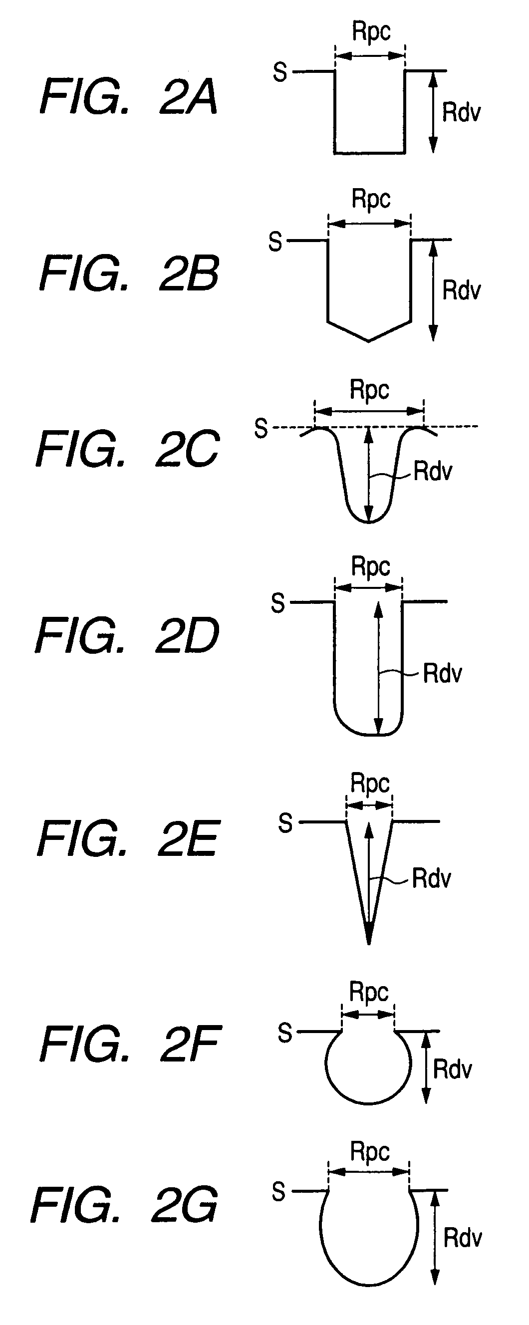
An electrophotographic photosensitive member is provided which has a photosensitive layer formed on a support. The electrophotographic photosensitive member has a surface layer containing a silicon-containing compound or a fluorine-containing compound. The surface layer has a plurality of depressed portions which are independent from one another, on the surface. When the major axis diameter of the depressed portion is represented by Rpc and the distance between the deepest part and the opening surface of the depressed portion is represented by Rdv, Rdv is 0.1μ or more to 10.0 μm or less, and the ratio of the depth (Rdv) to the major axis diameter (Rpc), Rdv / Rpc, is more than 0.3 to 7.0 or less.

Description

[0001]This application is a continuation of International Application No. PCT / JP2008 / 056638, filed Mar. 27, 2008, which claims the benefit of Japanese Patent Application No. 2007-085141, filed Mar. 28, 2007.BACKGROUND OF THE INVENTIONField of the Invention[0002]The present invention relates to an electrophotographic photosensitive member and a process cartridge and electrophotographic apparatus having the electrophotographic photosensitive member.[0003]An electrophotographic photosensitive member (hereinafter sometimes simply referred to as a “photosensitive member” or a “photosensitive drum”) is generally used in an electrophotographic image forming process, which is constituted of a charging step, an exposure step, a developing step, a transfer step and a cleaning step. Of the electrophotographic image forming process, the cleaning step for cleaning the circumference surface of an electrographic photosensitive member by removing toner called transfer-residual toner remaining on th...

Claims


Application Information

Patent Timeline
Patent Type & Authority Patents(United States)
IPC IPC(8): G03G15/00
CPCG03G5/147G03G5/14708G03G5/14717G03G5/14752G03G5/14756G03G5/14773
Inventor OKUDA, ATSUSHIOGAKI, HARUNOBUKITAMURA, WATARUUESUGI, HIROTOSHI
Owner CANON KK
Why Eureka
Try Eureka