
Prosthetic valves and associated appartuses, systems and methods

a technology appartuses, applied in the field of prosthetic heart valves, can solve the problems of increased hydrostatic pressure, changes in skin color, pain, swelling and edema, etc., and achieve the effect of reducing the risk of cpb and ensuring the accuracy of deploymen

Inactive Publication Date: 2016-10-06
MEDTRONIC INC
View PDF2 Cites 0 Cited by
  • Summary
  • Abstract
  • Description
  • Claims
  • Application Information

AI Technical Summary

Benefits of technology

This patent describes a new kind of prosthetic valve that can be used to replace damaged valves in humans. The new valve has several technical benefits. It is durable, can be implanted in a minimally invasive way, is easier to install, and can be reliably positioned during the procedure. The valve also reduces the risk of complications and improves safety. Additionally, it can be designed to reduce the impact on the valve tissue during the implant. The valve has an expandable frame with a concave inflow portion that makes it easy to position in the patient's body. The frame is made of wire cells interconnected with each other. Overall, the new prosthetic valve is designed to meet the same objectives as conventional valves but with improved durability and minimally invasive procedure.

Problems solved by technology

When valves exhibit abnormal anatomy and function as a result of valve disease or injury, the unidirectional flow of the physiological fluid they are designed to regulate is disrupted, resulting in increased hydrostatic pressure.
For example, venous valvular dysfunction leads to blood flowing back and pooling in the lower legs, resulting in pain, swelling and edema, changes in skin color, and skin ulcerations that can be extremely difficult to treat.
Lymphatic valve insufficiency can result in lymphedema with tissue fibrosis and gross distention of the affected body part.
Regardless of their etiology, all valvular diseases result in either stenosis, in which the valve does not open properly, impeding fluid flow across it and causing a rise in fluid pressure, or insufficiency / regurgitation, in which the valve does not close properly and the fluid leaks back across the valve, creating backflow.
However, open-heart valve repair or replacement surgery is a long and tedious procedure and involves a gross thoracotomy, usually in the form of a median sternotomy.

Method used


Image

  • Prosthetic valves and associated appartuses, systems and methods
  • Prosthetic valves and associated appartuses, systems and methods
  • Prosthetic valves and associated appartuses, systems and methods

Examples


Embodiment Construction

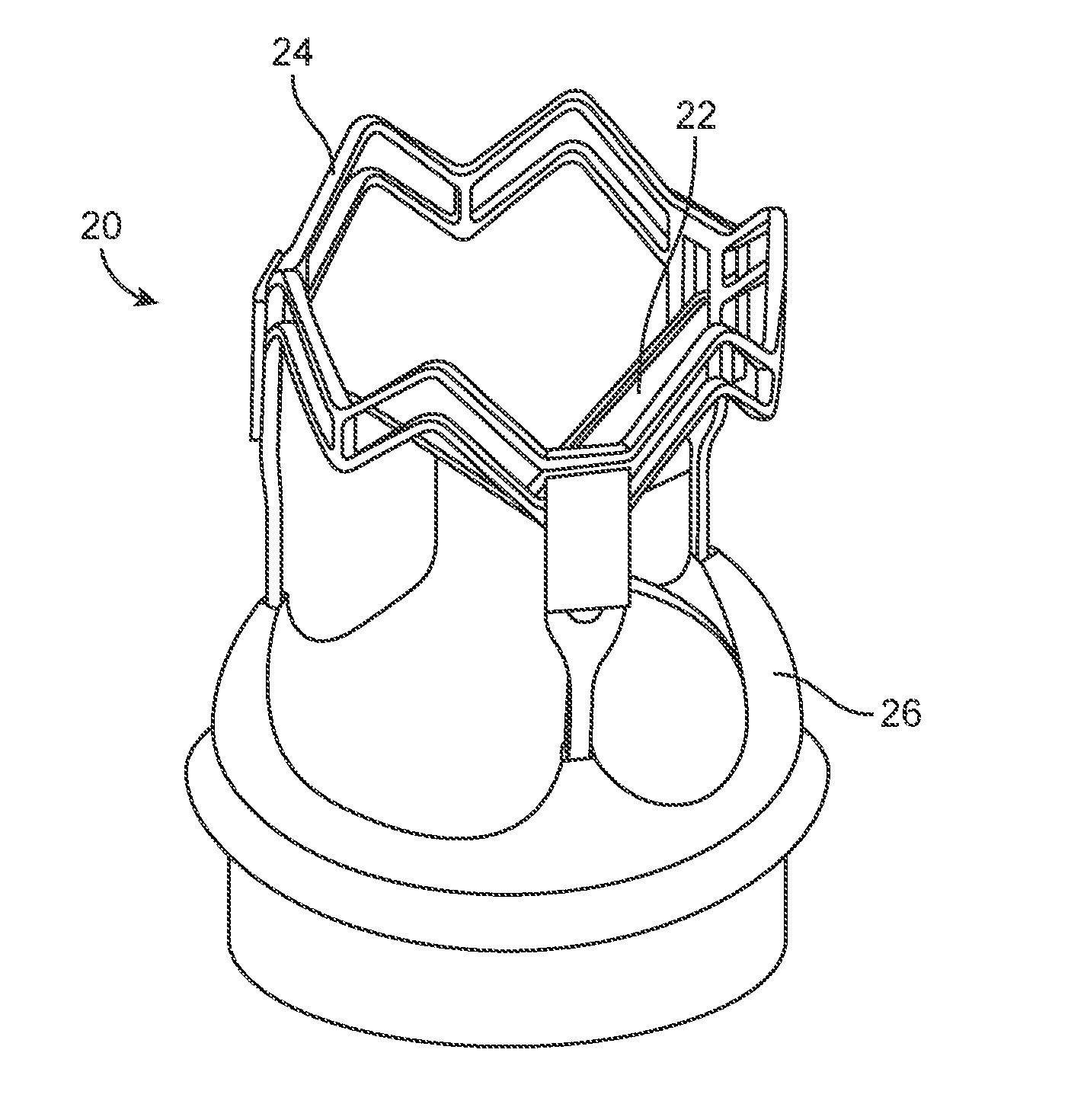
[0036]The present disclosure relates to prosthetic valves, such as heart valves, and methods, systems, and devices associated therewith. One or more embodiments of the prosthetic valves achieve one or more of the following objectives: (1) durability the same or better than convention replacement valves; (2) valve in valve suitability; (3) hemodynamics the same or better than conventional valves; (4) reproducible minimally invasive procedure; (5) ease of implant; (6) first time deployment accuracy; and (7) reduced cardiopulmonary bypass (CPB) and cross clamp times; (8) reduced complications and improved safety; and (9) improved implantability.

[0037]In some embodiments, a prosthetic valve described herein has one or more of the following features: (1) frame height suitable to accommodate aortotomy two centimeters above STJ maximum height, while being as short as possible; (2) avoidance of crown-like structure / rail in outflow; (3) maintain access to coronaries; (4) active fixation in i...


PUM


Abstract

A valve prosthesis includes an expandable frame comprising an outflow portion and an inflow portion connected to the outflow portion. The frame defines a central lumen extending between the outflow portion and the inflow portion. The frame is generally cylindrical in a fully expanded configuration. When the frame is in the fully expanded configuration, an outer surface of the inflow portion is concave. The inflow portion has an upper inflow portion and a lower inflow portion. When the frame is in the fully expanded configuration, the upper inflow portion flares outwardly from the central lumen of the frame to greater extent than the lower inflow portion.

Description

RELATED APPLICATIONS[0001]This application claims the benefit of U.S. Provisional Patent Application No. 61 / 819,486, filed on May 3, 2013, and U.S. Provisional Patent Application No. 61 / 930,912, filed on Jan. 23, 2014, each of which Provisional Patent Applications are hereby incorporated herein by reference in their respective entireties to the extent that they do not conflict with the disclosure presented herein.FIELD[0002]The present disclosure relates to, among other things, prosthetic heart valves, and associated apparatuses and methods of use, manufacture and treatment.BACKGROUND[0003]The transport of vital fluids in the human body is largely regulated by valves. Physiological valves are designed to prevent the backflow of bodily fluids, such as blood, lymph, urine, bile, etc., thereby keeping the body's fluid dynamics unidirectional for proper homeostasis. For example, venous valves maintain the upward flow of blood, particularly from the lower extremities, back toward the hea...

Claims


Application Information

Patent Timeline
IPC IPC(8): A61F2/24A61F2/07
CPCA61F2/2418A61F2/2409A61F2250/0039A61F2/07A61F2230/0069A61F2/2469A61F2220/0075A61F2/2476A61F2/82
Inventor GLOSS, MICHAELGROEN, TIMOTHYMAJKRZAK, CAROLYNRUST, MATTHEWRYAN, TIMOTHYWESTON, MATTHEW
Owner MEDTRONIC INC
Learn More