Speaker system

a speaker system and speaker technology, applied in the field of speaker systems, can solve the problems of small speaker systems that have difficulty in realizing a speaker system capable of satisfactory bass reproduction, and achieve the effects of improving sound quality, reducing pressure variation in the sealed chamber, and increasing volume of sealed spa

Active Publication Date: 2007-06-07
PANASONIC CORP
View PDF6 Cites 56 Cited by
  • Summary
  • Abstract
  • Description
  • Claims
  • Application Information

AI Technical Summary

Benefits of technology

[0023] According to the aforementioned first aspect, the plate member of the variable mechanism is displaced in accordance with at least the pressure variation of the direct current component, the pressure variation occurring in the sealed chamber. As a result, a volume of the sealed space increases or decreases, thereby reducing the pressure variation in the sealed chamber. Thus, the speaker system of the present invention is capable of having stable acoustic performance without being influenced by the pressure variation. Furthermore, the adsorption member is disposed in the sealed chamber which is sealed from the outside air, whereby it becomes possible to realize a speaker system in which deterioration of the adsorption member is suppressed for a long period of time. Specifically, according to the present invention, the stable acoustic performance can be ensured even if an environmental condition of the speaker system changes, and an extension of a bass reproduction range realized by the adsorption member can be maintained for a long period of time.
[0024] According to the aforementioned second and third aspects, since the adsorption member is made of activated carbon or other porous materials, a volume of the cabinet equivalently increases, whereby even a small cabinet allows the bass reproduction range to be extended.
[0025] According to the aforementioned fourth aspect, the plate member of the variable mechanism is displaced, more easily than the diaphragm of the speaker unit, in accordance with at least the pressure variation of the direct current component, the pressure variation occurring in the sealed chamber. Thus, it becomes possible not to exert on the speaker unit a direct influence caused by the pressure variation. Furthermore, the resonance frequency of the variable mechanism is lower than that of the speaker unit, thereby suppressing a vibration generated by the variable mechanism in accordance with the pressure variation in the reproduction frequency range of the speaker unit. Specifically, the variable mechanism is displaced in accordance with at least th

Problems solved by technology

In general, a small speaker system has a difficulty in realizing a speaker system capable of

Method used


Image

  • Speaker system
  • Speaker system
  • Speaker system

Examples


first embodiment

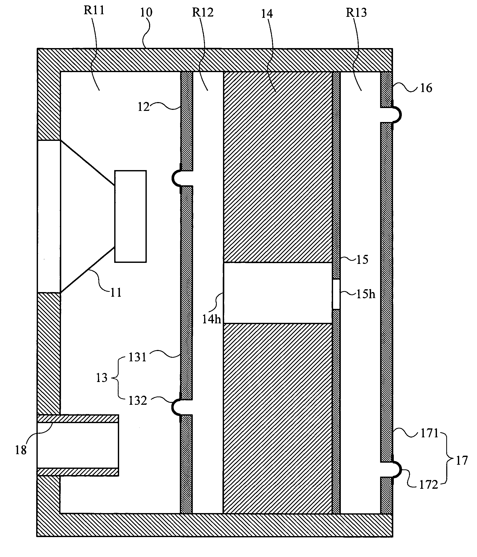
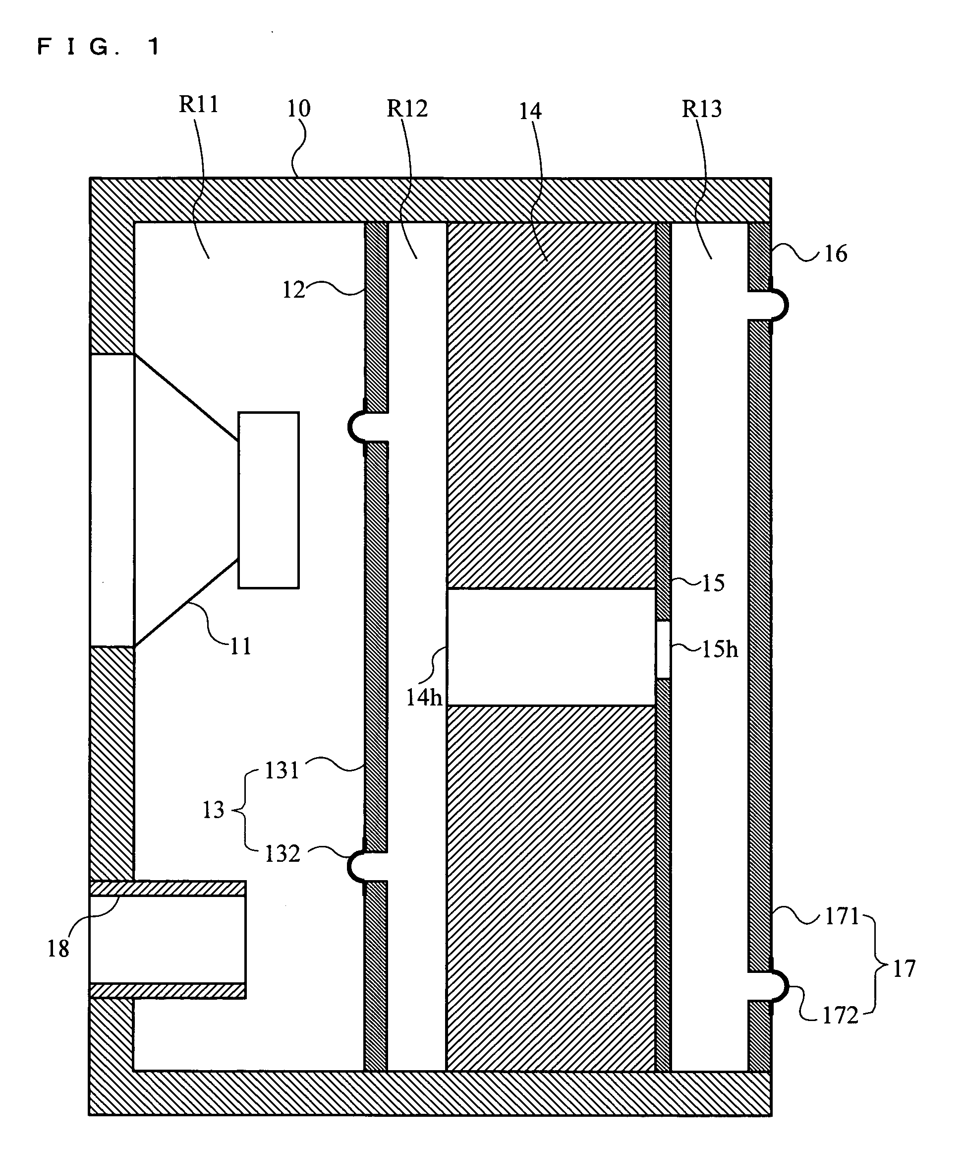
[0055] A speaker system according to a first embodiment of the present invention is described with reference to FIG. 1. FIG. 1 is a cross-sectional view illustrating a structure of a speaker system according to the first embodiment.

[0056] In FIG. 1, the speaker system includes a cabinet 10, a speaker unit 11, a first parting board 12, a drone cone 13, an adsorption member 14, a second parting board 15, a backboard 16, a variable mechanism 17, and a port 18. As shown in FIG. 1, the speaker system according to the first embodiment is a phase inversion type speaker.

[0057] The cabinet 10 is defined by a front face, upper face, bottom face, and left and right side faces of a housing of the speaker system. The speaker unit 11 is a dynamic speaker, for example. The speaker unit 11 is attached to an opening formed in the front of the cabinet 10 such that a sound emission surface of the speaker unit 11 faces an exterior of the cabinet 10. The backboard 16 including the variable mechanism 1...

second embodiment

[0081] A speaker system according to a second embodiment of the present invention is described with reference to FIG. 3. FIG. 3 is a cross-sectional view illustrating a structure of a speaker system according to the second embodiment.

[0082] In FIG. 3, the speaker system includes a cabinet 20, a speaker unit 21, an adsorption member 24, a backboard 26, and a variable mechanism 27. As shown in FIG. 3, the speaker system according to the second embodiment is a closed enclosure type speaker. The speaker unit 21, the first parting board 25, and the backboard 26 in the second embodiment have the same functions as the speaker unit 11, the second parting board 15, and the backboard 16 in the first embodiment, respectively. Thus, detailed descriptions thereof are omitted here. The adsorption member 24 is similar to the adsorption member 14 in the first embodiment except that these adsorption members have different shapes.

[0083] The cabinet 20 is defined by a front face, upper face, bottom ...

third embodiment

[0102] A speaker system according to a third embodiment of the present invention is described with reference to FIG. 5. FIG. 5 is a cross-sectional view illustrating a structure of a speaker system according to the third embodiment.

[0103] In FIG. 5, the speaker system includes a cabinet 30, a speaker unit 31, an adsorption member 34, a backboard 36, and a variable mechanism 37. As shown in FIG. 5, the speaker system according to the third embodiment is a closed enclosure type speaker having a chamber R31 enclosed by the cabinet 30 and the backboard 36. The speaker unit 31 and the backboard 36 in the third embodiment have the same functions as the speaker unit 11 and the backboard 16 in the first embodiment, respectively. Thus, detailed descriptions thereof are omitted here. The adsorption member 34 is similar to the adsorption member 14 in the first embodiment except that these adsorption members have different shapes.

[0104] The cabinet 30 is defined by a front face, upper face, b...


PUM


Abstract

A speaker system according to the present invention comprises a cabinet (10), a speaker unit (11), a first parting board (12), a drone cone (13), an adsorption member (14), a second parting board (15), a backboard (16), a variable mechanism (17), and a port (18). A sound pressure generated by the speaker unit (11) causes a pressure variation in a second chamber (R12) via the drone cone (13). The adsorption member (14) with an effect of physical adsorption is operable to suppress the pressure variation. Furthermore, by displacing the diaphragm (171), the variable mechanism (17) is operable to reduce a pressure variation of a direct current component, which is caused by variations in ambient temperature or atmospheric pressure of the speaker system.

Description

TECHNICAL FIELD [0001] The present invention relates to a speaker system. More particularly, the present invention relates to a speaker system which implements satisfactory bass reproduction using a small speaker cabinet. BACKGROUND ART [0002] In general, a small speaker system has a difficulty in realizing a speaker system capable of satisfactory bass reproduction due to acoustic stiffness of a chamber of a speaker cabinet. Conventionally, in order to realize satisfactory bass reproduction in the small speaker system, there is a speaker system in which an activated carbon body is provided in the cabinet as a means of solving a problem of a bass reproduction limit which is determined based on a cabinet volume (see patent document 1, for example). [0003]FIG. 9 is a cross-sectional view illustrating a main portion of a conventional speaker system. In FIG. 9, the speaker system comprises a cabinet 101, a woofer 102, an activated carbon 103, a supporting member 104, a diaphragm 105, and...

Claims


Application Information

Patent Timeline
IPC IPC(8): H04R1/02H04R1/20A47B81/06H04R1/28H04R5/02
CPCH04R1/2803H04R1/2819H04R1/2834H04R5/023H04R2499/13H04R2499/15
Inventor SAIKI, SHUJIKUZE, MITSUKAZUMATSUMURA, TOSHIYUKIKANO, SAWAKO
Owner PANASONIC CORP
Why Eureka
Try Eureka