Fluid pump apparatus

a pump and fluid technology, applied in the direction of machines/engines, stators, liquid fuel engines, etc., can solve the problem that the total fan noise in the audible frequency band of human beings cannot be reduced, and achieve the effect of reducing the pressure variation of fluid, reducing the fan noise (wind noise), and cross-sectional area of the vortex flow chamber

Inactive Publication Date: 2005-10-06
DENSO CORP
View PDF6 Cites 11 Cited by
  • Summary
  • Abstract
  • Description
  • Claims
  • Application Information

AI Technical Summary

Benefits of technology

[0008] The present invention is made in view of the above problems, and it is an object of the present invention to provide a fluid pump apparatus which reduces noises audible to the human beings to a small amount, by moving peak frequency of the noises to a higher value out of the audible frequency band.
[0010] The frequency (N×S) of fan noises at a primary peak, according to the above feature, appears at higher frequencies out of the audible frequency band, so that the noises audible to the human beings can be reduced.
[0012] The peak frequencies of the fan noises can be centralized on one point (frequency) according to such feature, and the variation of the peak frequency at the primary peak is avoided. As a result, the frequency of the fan noises at the primary peak can be completely moved to the higher frequency out of the audible frequency band.
[0013] According to a further feature of the present invention, the number of blades of the impeller is so made to be a prime number, so that fan noises are prevented from appearing at other frequencies than that of the primary peak. As a result, the fan noises of 0.5 peak are prevented from generating in the audible frequency band to the human beings. The peak frequencies of the fan noises are prevented from de-concentrating and the peak frequency of the fan noises are prevented from generating in audible frequency band.
[0015] According to the volume decreasing means, a cross sectional area of the vortex flow chamber is gradually decreased at the ending portion of the vortex flow chamber in a rotational direction of the impeller (blades), so that pressure variation of the fluid is decreased when the blades come across the partitioning portion, to thereby reduce the fan noise (wind noise). With this arrangement, the fan noises can be reduced, in particular, when the primary peak of the fan noises passes through the audible frequency band during periods of starting and stopping the air pump.

Problems solved by technology

As a result, the total fan noises in the audible frequency band to human beings can not be reduced.

Method used


Image

  • Fluid pump apparatus
  • Fluid pump apparatus
  • Fluid pump apparatus

Examples


first embodiment

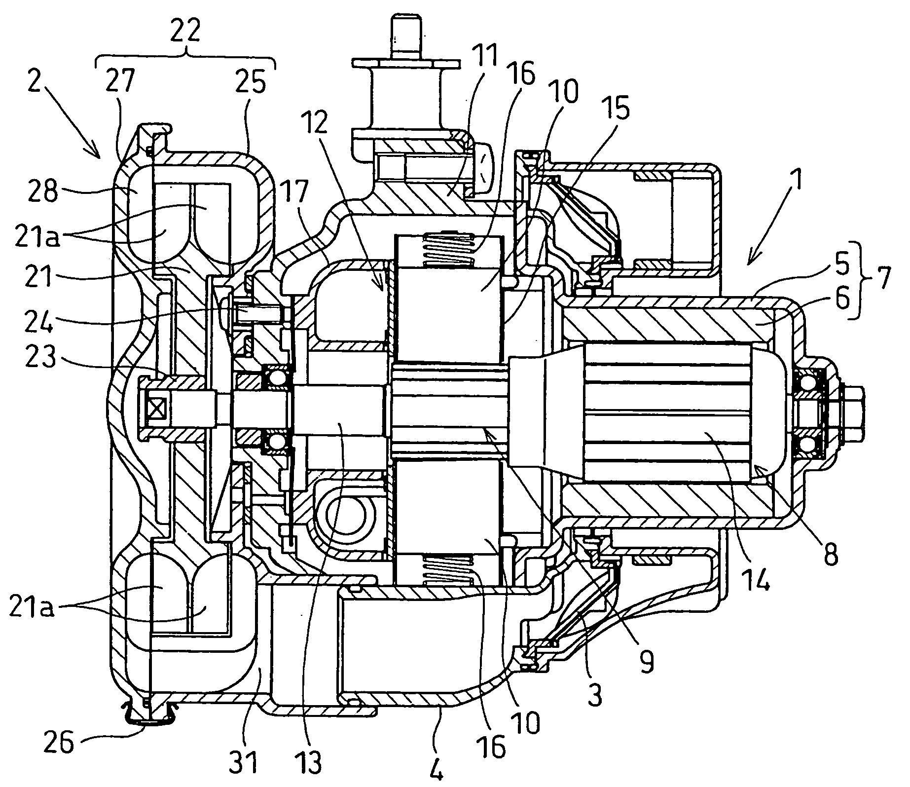
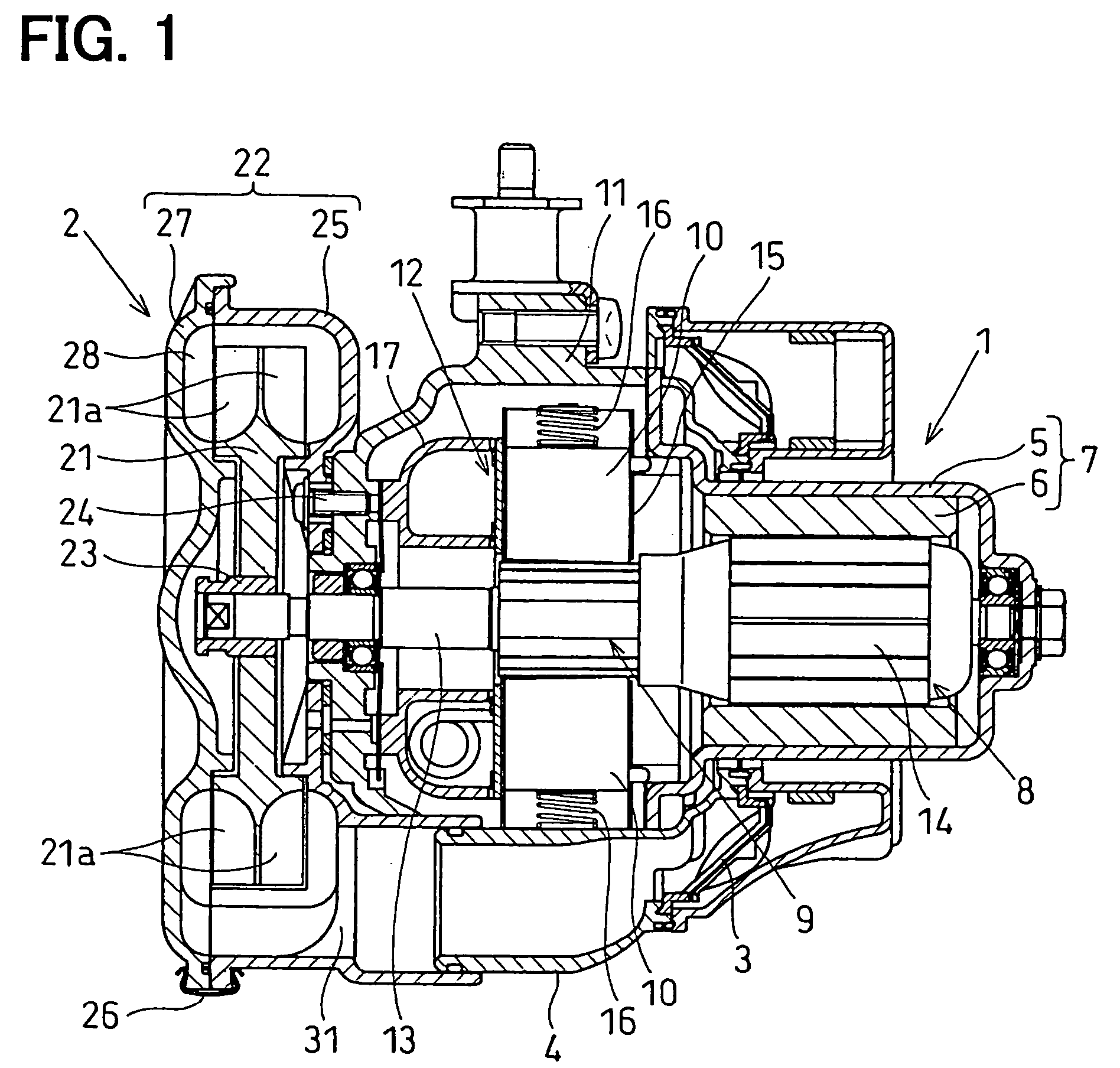
[0023] The present invention will be explained below with reference to the embodiment, in which the present invention is applied to an electrical air supply pump, as shown in FIGS. 1 to 3.

[0024] The air supply pump compresses air and pumps out the compressed air. The air supply pump is used, for example, in a secondary air supply system for an automotive engine, wherein the air supply pump supplies the compressed air into an exhaust pipe of the engine at an upstream side of a catalyst for purifying the exhaust gas.

[0025] The air supply pump, which comprises a blower device having a double-blade and vortex flow type impeller, is shown as an example in the first embodiment.

[0026] The air supply pump, as shown in FIG. 1, comprises an electric motor 1, the above mentioned blower device 2, and an air duct portion 4 in which a filter 3 is arranged.

(Electric Motor)

[0027] The electric motor 1 of this embodiment is a DC motor, which comprises a stator 7 having a cylindrical yoke 5 and ...


PUM


Abstract

In an air supply pump, having an electric motor and a blower driven by the electric motor, the blower has an impeller having multiple blades for compressing and pumping out the air. A value (F) obtained by a formula (F=N×S) is made to be higher than the audible frequency band to the human beings, wherein “N” means number of blades of the impeller, and “S” means a number of rotation of the impeller for each second at a normal rotational speed. (“×” is a symbol for a mathematical multiplication.) The frequency (F=N×S) of fan noises at a primary peak appears at higher frequencies out of the audible frequency band, so that the noises audible to the human beings can be reduced.

Description

CROSS REFERENCE TO RELATED APPLICATION [0001] This application is based on Japanese Patent Application No. 2004-109909 filed on Apr. 2, 2004, the disclosure of which is incorporated herein by reference. FIELD OF THE INVENTION [0002] This invention relates to a fluid pump apparatus, which compresses and pumps out fluid by rotation of an impeller having multiple blades, and in particular to an air supply pump in which fan noises can be reduced. BACKGROUND OF THE INVENTION [0003] The following technical features are known in the art to reduce fan noises of an electrical air pump, for example, as disclosed in Japanese Patent Publication No. H9-209997; [0004] (1) pitch angles of respective blades are designed to be non-uniform to each other, and [0005] (2) positions of blades, which are formed on both sides of an impeller, are designed to be displaced by a half pitch in a rotational direction of the impeller, at a position at which a modulation point is zero. [0006] According to the abov...

Claims


Application Information

Patent Timeline
Patent Type & Authority Applications(United States)
IPC IPC(8): F04D29/38F01D5/10F04D23/00F04D29/44F04D29/66
CPCF04D23/008F04D29/663F04D29/161
Inventor TSUZUKI, KUNIHIROYOKOYAMA, SHINICHIUCHIDA, AKIKAZU
Owner DENSO CORP
Why Eureka
Try Eureka