Method for controlling a vehicle

a technology for controlling a vehicle and a driveline, applied in the direction of brake systems, machines/engines, engine starters, etc., can solve the problems of reducing the possibility of increasing the gear lash or reducing the chain tension in the driveline, limiting the possibility of increasing the gear lash or reducing the chain tension, etc., to reduce the possibility of impact loads, increase the gear lash, and the effect of positive torqu

Active Publication Date: 2015-08-18
FORD GLOBAL TECH LLC
View PDF13 Cites 2 Cited by
  • Summary
  • Abstract
  • Description
  • Claims
  • Application Information

AI Technical Summary

Benefits of technology

[0004]By holding vehicle brakes in an applied state in response to a road grade, it may be possible to reduce the possibility of impact loads between gear teeth or within chain drives when the engine is restarted and positive torque is applied to the driveline. For example, if road grade is zero, vehicle brakes may be released when a driver releases a brake pedal. On the other hand, if the road grade is non-zero and negative, the vehicle brakes may be released after engine speed reaches a threshold speed where a torque converter transfers positive torque to the driveline. Holding the vehicle brakes in an applied state limits the possibility of increasing gear lash or reducing chain tension in the driveline.
[0005]The present description may provide several advantages. In particular, the approach may reduce audible driveline noise. Additionally, the approach may reduce driveline degradation. Further, the approach may improve vehicle drivability.

Problems solved by technology

If the vehicle is stopped on a downhill grade and the engine is automatically restarted while a gear is engaged, the vehicle driveline lash may initially increase, due to an increase in gear tooth to tooth spacing or a loss of tension in a chain drive, due to the negative grade.
The impact load between gear teeth or within a chain drive may provide an undesirable audible sound as well as gear tooth or chain drive degradation.
Holding the vehicle brakes in an applied state limits the possibility of increasing gear lash or reducing chain tension in the driveline.

Method used


Image

  • Method for controlling a vehicle
  • Method for controlling a vehicle
  • Method for controlling a vehicle

Examples


Embodiment Construction

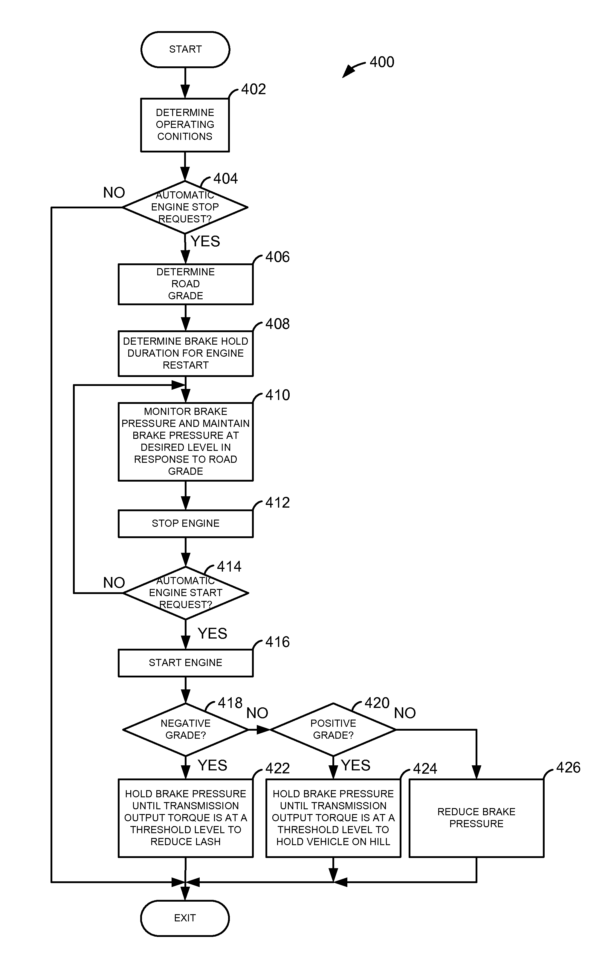
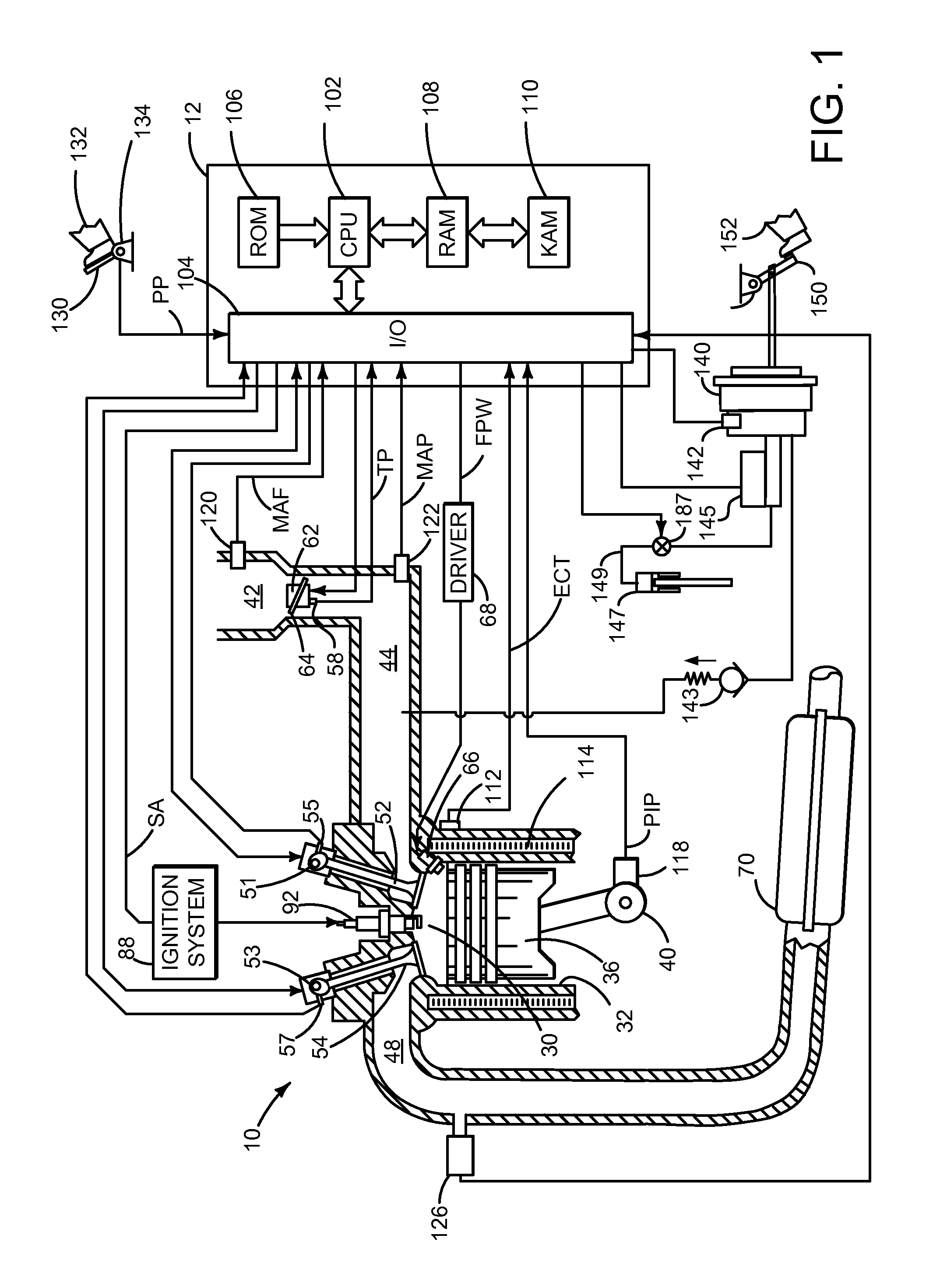
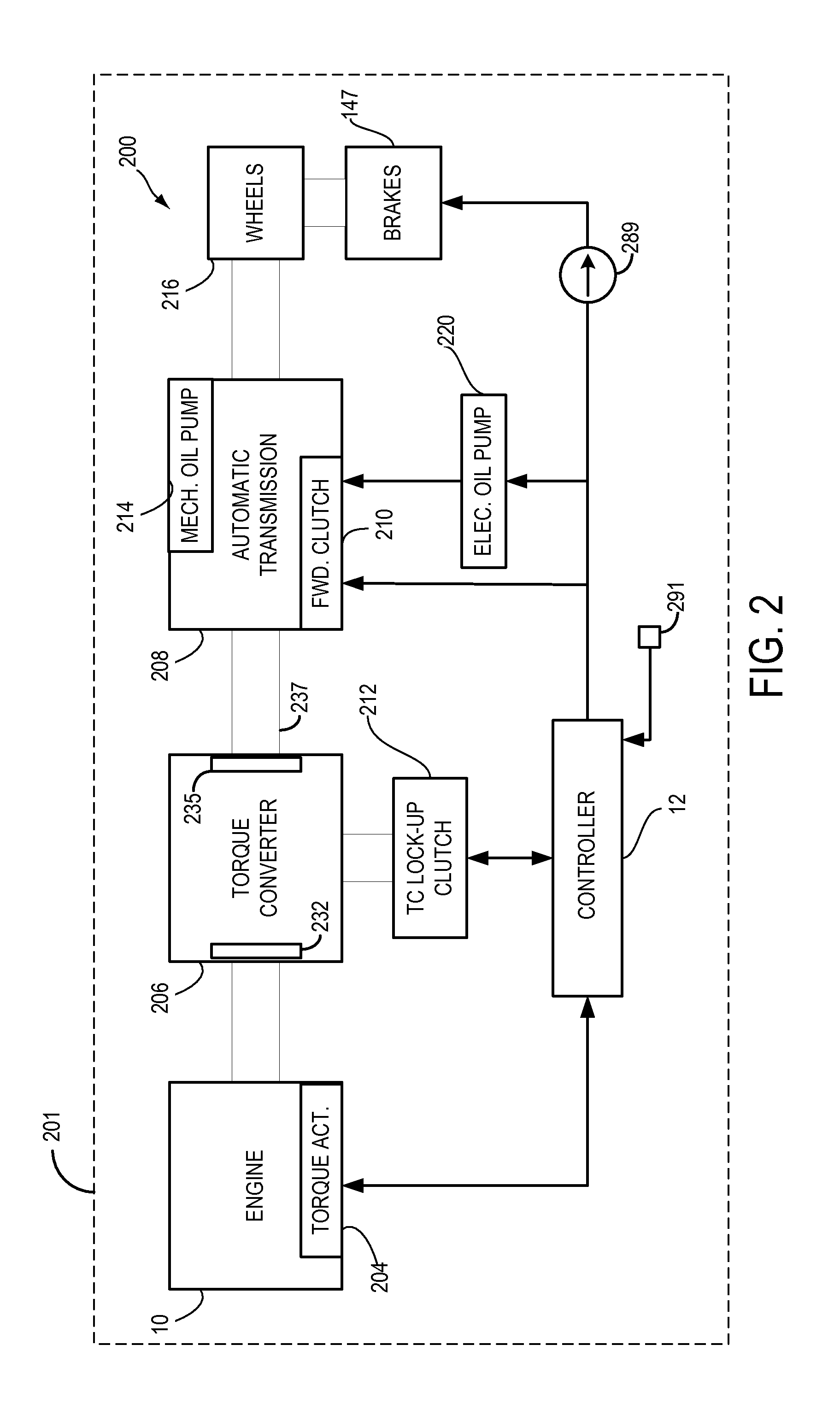
[0013]The present description is related to controlling operation of a vehicle. In one non-limiting example, the vehicle may include an engine as illustrated in FIG. 1. Further, the engine may be part of a vehicle as illustrated in FIG. 2. The vehicle may operate according to the method of FIG. 4 and as shown in FIG. 3.

[0014]Referring to FIG. 1, internal combustion engine 10, comprising a plurality of cylinders, one cylinder of which is shown in FIG. 1, is controlled by electronic engine controller 12. Engine 10 includes combustion chamber 30 and cylinder walls 32 with piston 36 positioned therein and connected to crankshaft 40. Combustion chamber 30 is shown communicating with intake manifold 44 and exhaust manifold 48 via respective intake valve 52 and exhaust valve 54. Each intake and exhaust valve may be operated by an intake cam 51 and an exhaust cam 53. The position of intake cam 51 may be determined by intake cam sensor 55. The position of exhaust cam 53 may be determined by ...


PUM


Abstract

A method for improving starting of an engine that may be repeatedly stopped and started is presented. In one example, the method adjusts application of vehicle brakes to reduce the possibility of impact between gear teeth after engine starting.

Description

FIELD[0001]The present description relates to a system for improving vehicle operation. The method may be particularly useful for vehicles that include engines that are often automatically stopped and then restarted.BACKGROUND AND SUMMARY[0002]An engine of a vehicle may be automatically stopped during select conditions to conserve fuel. The engine may be restarted during other conditions when it is desirable to move the vehicle. Some vehicles that are automatically stopped may include an automatic transmission. The transmission may be in a selected gear at the time the engine is stopped. If the vehicle is stopped on a downhill grade and the engine is automatically restarted while a gear is engaged, the vehicle driveline lash may initially increase, due to an increase in gear tooth to tooth spacing or a loss of tension in a chain drive, due to the negative grade. The increased lash may be taken up suddenly and a tooth to tooth, or chain link, impact load may occur after the engine is...

Claims


Application Information

Patent Timeline
Patent Type & Authority Patents(United States)
IPC IPC(8): B60W10/184B60W10/06
CPCB60W10/184B60W10/06Y10T477/814B60W10/18B60W30/18B60W40/076B60W2510/0638B60W2552/15B60T7/122B60W30/18118F02N11/0818F02N2200/0801F02N2200/102F02N2200/124Y02T10/40
Inventor GIBSON, ALEX O'CONNORSIMON, MICHAEL M. S.DOERING, JEFFREY ALLEN
Owner FORD GLOBAL TECH LLC
Why Eureka
Try Eureka