
Infrared-type gas detector

a gas detector and infrared technology, applied in the field of infrared-type gas detectors, can solve the problem of unevenness in and achieve the effect of restricting the unevenness of the gap of the fabry-perot filter

Active Publication Date: 2009-04-07
DENSO CORP
View PDF5 Cites 11 Cited by
  • Summary
  • Abstract
  • Description
  • Claims
  • Application Information

AI Technical Summary

Benefits of technology

[0007]In view of the above-described disadvantage, it is an object of the present invention to provide an infrared-type gas detector where unevenness in a gap of a Fabry-Perot filter is reduced.
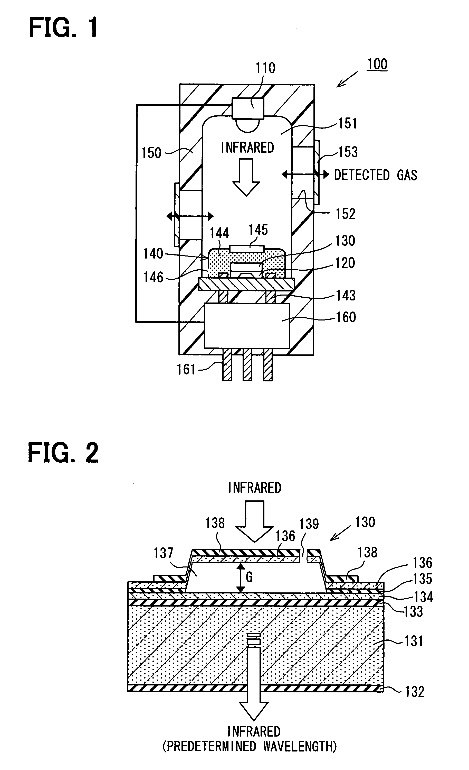
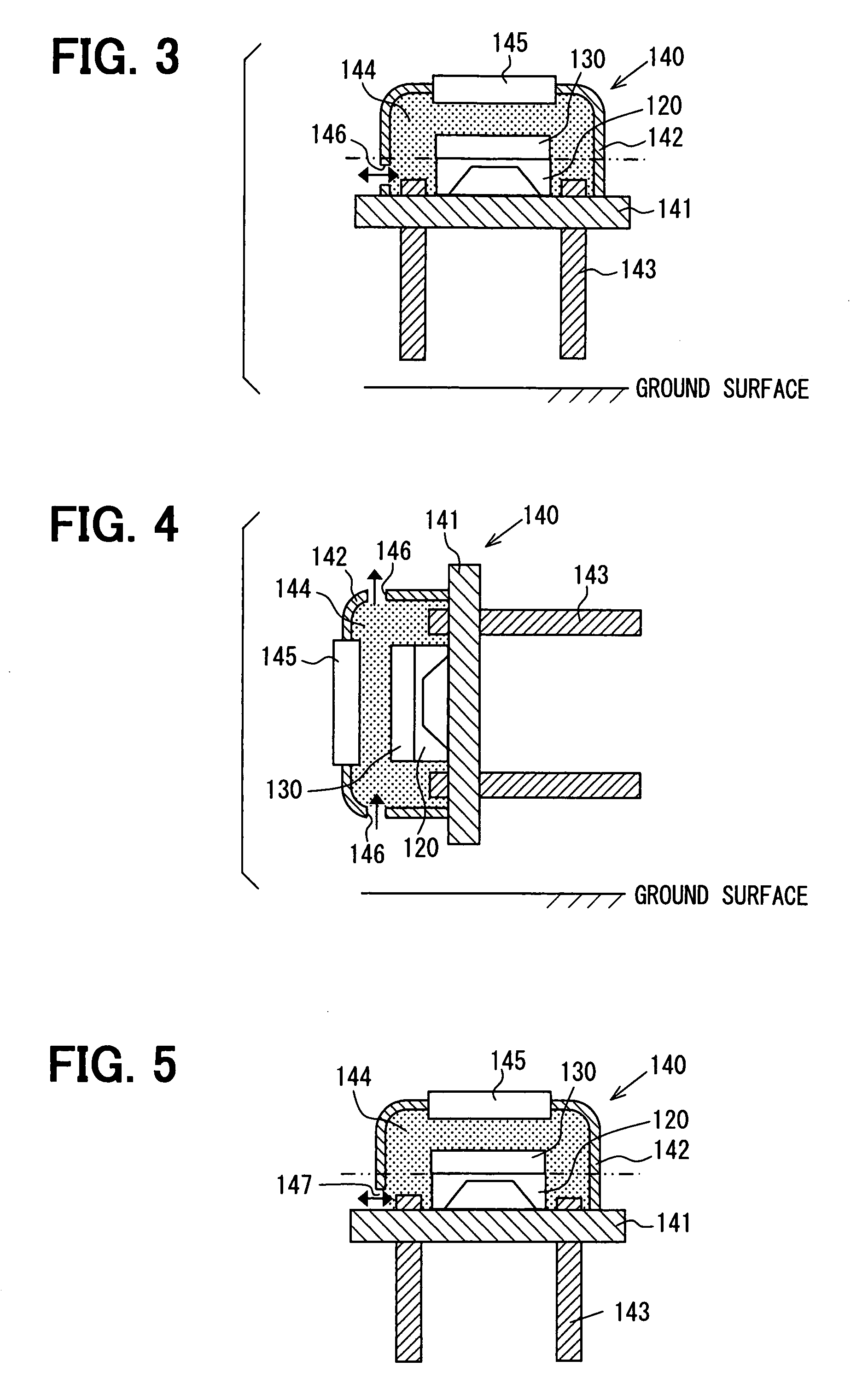
[0009]Because the ventilation portion constructs a passage for communicating the interior of the case member and the exterior thereof, the pressure variation of the inner space due to the temperature variation thereof can be lowered. Thus, the unevenness of the gap of the Fabry-Perot filter can be restricted.
[0011]Because the inner space of the case member is set in the pressure-reducing state as compared with the atmospheric pressure, the pressure variation of the inner space due to the temperature variation thereof can be lowered. Thus, the unevenness of the gap of the Fabry-Perot filter can be restricted.
[0013]In this case, at lease one of the temperature variation of the inner space and the pressure variation thereof due to the temperature variation which cause the unevenness of the gap of the Fabry-Perot filter can be detected. Furthermore, the control unit can correct and control the voltage applied between the fixed electrode and the moving electrode based on the detection result of the second detection unit, so that the gap of the Fabry-Perot filter keeps constant to be unrelated to the temperature variation (pressure variation) of the inner space. Thus, the unevenness of the gap of the Fabry-Perot filter can be restricted.

Problems solved by technology

That is, unevenness will occur in the gap of the Fabry-Perot filter due to the variation (that is, variation of resistance due to gas) in the pressure of the inner space, even when the applied voltage is same.

Method used


Image

  • Infrared-type gas detector
  • Infrared-type gas detector
  • Infrared-type gas detector

Examples


embodiments

First Embodiment

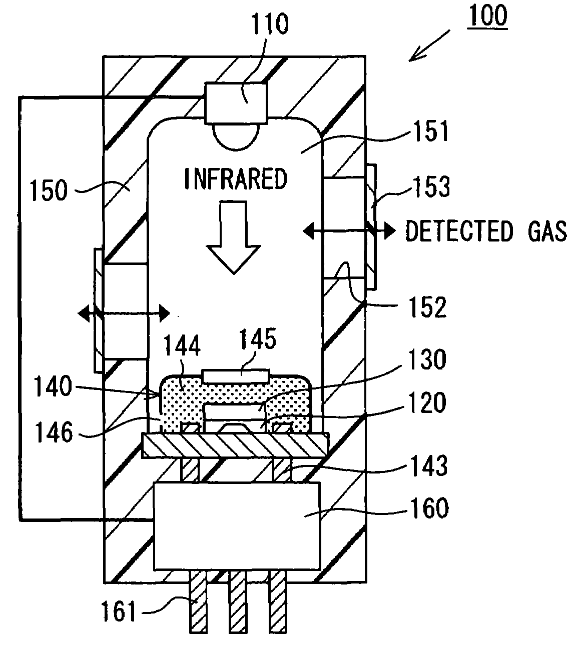
[0024]An infrared-type gas detector 100 according to a first embodiment of the present invention will be described with reference to FIGS. 1-5. As shown in FIG. 1, the infrared-type gas detector 100 has a light source 110 for radiating infrared, a first detection unit 120 for detecting infrared, a Fabry-Perot filter 130 which is arranged at a light path of the infrared from the light source 110 to the first detection unit 120 and through which the infrared having a predetermined wavelength passes (that is, infrared selectively passes Fabry-Perot filter 130), a can package member 140 (case member) in which the first detection unit 120 and the Fabry-Perot filter 130 are housed, and a housing 150 in which the light source 110, the first detection unit 120, the Fabry-Perot filter 130 and the case member 140 are accommodated.

[0025]The light source 110 can be constructed of any source which radiates the infrared having a predetermined wavelength field. For example, the lig...

second embodiment

[0066]A second embodiment of the present invention is described with reference to FIG. 6.

[0067]In the above-described first embodiment, the ventilation portion (for example, through hole 146 and gap 147) is arranged at the case member 140 where the first detection unit 120 and the Fabry-Perot filter 130 are housed, to restrict the unevenness of the gap G of the Fabry-Perot filter 130. According to the second embodiment, as shown in FIG. 6, the inner space 144 of the case member 140 is substantially hermetically sealed and set at a pressure-reducing state (e.g., vacuum state) as compared with the atmosphere.

[0068]According to the second embodiment, because the inner space 144 of the case member 140 is in the decompression state (attenuated state) as compared with the atmosphere, the pressure variation (unevenness of resistance due to gas) of the inner space 144 in response to the temperature variation can be reduced as compared with the conventional device where the pressure in the i...

third embodiment

[0072]A third embodiment of the present invention is described with reference to FIG. 7.

[0073]According to the above-described second embodiment, the inner space 144 is provided with the decompression state (pressure-reducing state) as compared with the atmosphere to reduce the unevenness of the gap G of the Fabry-Perot filter 130. In contrast, according to the third embodiment, the pressure state of the inner space 144 is not specially limited, while a second detection unit 170 is arranged in the inner space 144 of the case member 140 to detect at least one of the temperature and the pressure in the inner space 144. Based on the detection result of the detection unit, the control unit (correction control unit) of the circuit chip 160 can correct and control the voltage applied to the Fabry-Perot filter 130.

[0074]As shown in FIG. 7, the second detection unit 170 (e.g., pressure sensor) is arranged in the inner space 144 of the case member 140. The second detection unit 170 is constr...


PUM

PropertyMeasurementUnit
wavelength fieldaaaaaaaaaa
central wavelengthaaaaaaaaaa
specific wavelengthaaaaaaaaaa

Abstract

An infrared-type gas detector is provided with a Fabry-Perot filter through which infrared having a predetermined wavelength is selected to pass, a first detection unit for receiving the infrared having passed through the Fabry-Perot filter and outputting a detection signal corresponding to an absorption amount of the infrared, and a case member having a window portion through which the infrared passes and housing therein the first detection unit and the Fabry-Perot filter in an inner space of the case member. The case member has at least one ventilation portion through which the inner space of the case member is communicated with the exterior of the case member.

Description

CROSS REFERENCE TO RELATED APPLICATION[0001]This application is based on a Japanese Patent Application No. 2006-247124 filed on Sep. 12, 2006, the disclosure of which is incorporated herein by reference.FIELD OF THE INVENTION[0002]The present invention relates to an infrared-type gas detector.BACKGROUND OF THE INVENTION[0003]Generally, an infrared-type gas detector is provided to detect a concentration of a detected gas according to an absorption amount of infrared which has a particular wavelength and absorbed by the detected gas. For example, with reference to JP-7-286809A and JP-2001-228326A, the infrared-type gas detector is provided with a Fabry-Perot filter.[0004]The Fabry-Perot filter has a fixed mirror and a moving mirror which faces the fixed mirror and is separated from the moving mirror with a predetermined gap. A predetermined voltage is applied between a fixed electrode arranged at the fixed mirror and a movable electrode arranged at the moving mirror, so that the movin...

Claims


Application Information

Patent Timeline
Patent Type & Authority Patents(United States)
IPC IPC(8): G01N21/00G01N21/35G01N21/3504
CPCG01N21/3504G01J3/26G01J3/42G01J5/12
Inventor YOSHIDA, TAKAHIKO
Owner DENSO CORP
Learn More