Method for producing a color filter

a color filter and color film technology, applied in the field of high-quality color filters, can solve the problems of uneven gap and breakage of ito film formed on the color filter, and achieve the effect of reducing the uneven gap with respect to the oppositely facing substra

Inactive Publication Date: 2011-05-24
DAI NIPPON PRINTING CO LTD
View PDF11 Cites 1 Cited by
  • Summary
  • Abstract
  • Description
  • Claims
  • Application Information

AI Technical Summary

Benefits of technology

[0013]According to the present invention, the film thickness of the portion with the colored layer and the light shielding part superimposed can be made lower. Moreover, in the case where a color filter of the present invention is, for example, a color filter having a stripe type colored layer, also concerning the portion with the stripe type colored layer and the light shielding part laminated, wherein with the stripe type colored layer and the light shielding part provided orthogonally, the film thickness of the stripe type colored layer formed on the thick film region of the light shielding part can be made smaller. Thereby, at the time of using a color filter of the present invention for a liquid crystal display apparatus, occurrence of such as a disturbance of the alignment of the liquid crystal layer formed on the color filter, breakage of the ITO film, unevenness of the gap with respect to the oppositely facing substrate can be reduced.

Problems solved by technology

In the case where the color filter has a difference in a film thickness between the region with the light shielding part and the colored layer laminated and the region with only the colored layer formed accordingly, the problems such as a disturbance of the alignment of the liquid crystal in the liquid crystal layer formed on the color filter so as to generate the light leakage, or breakage of the ITO film formed on the color filter have been generated.
Furthermore, the problem such as causing unevenness of the gap at the time of disposing the color filter and the counter substrate to face to each other has been involved.
Moreover, since the difference in the film thickness continues like a line in the a direction, it may become a cause of further disturbing the liquid crystal alignment or a cause of generating the breakage of the ITO film.

Method used


Image

  • Method for producing a color filter
  • Method for producing a color filter
  • Method for producing a color filter

Examples


first embodiment

1. First Embodiment

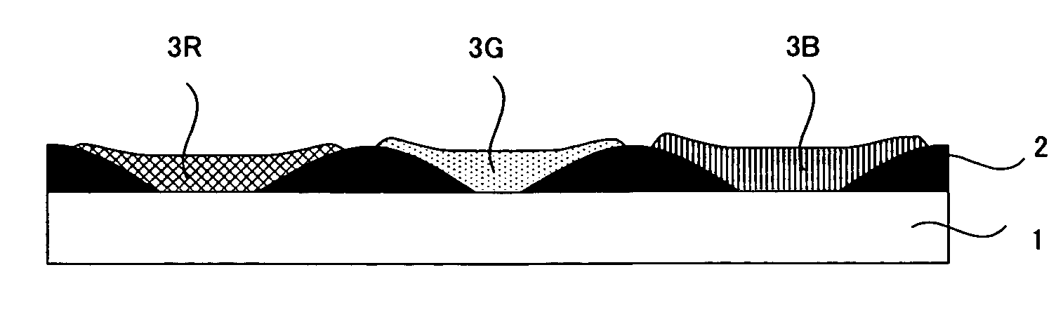
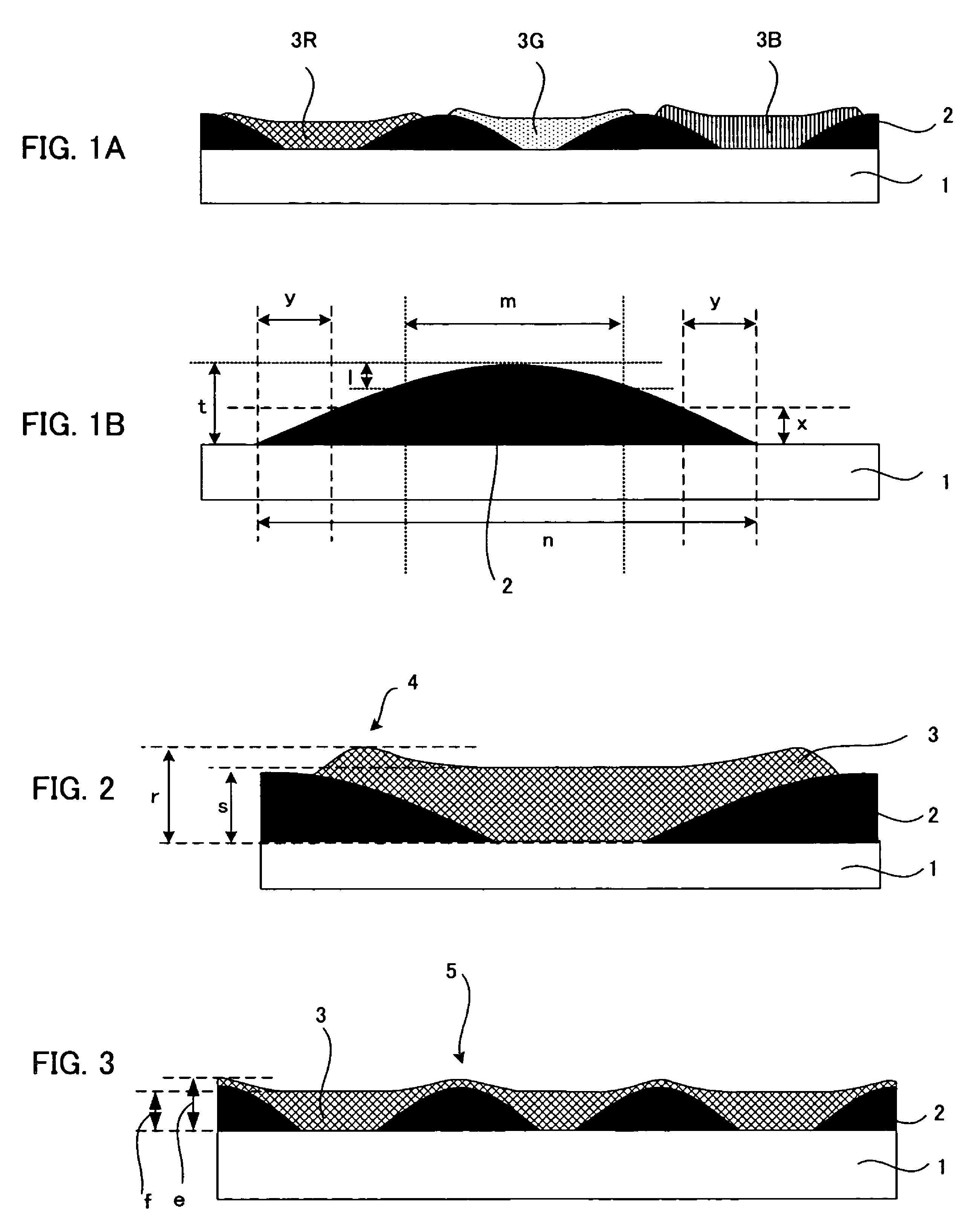
[0026]First, a first embodiment of the color filter of the present invention will be explained. The first embodiment of the color filter of the present invention is a color filter comprising: a transparent substrate; a light shielding part formed on the transparent substrate and contains at least a light shielding material and a resin; and a colored layer formed in the opening part of the light shielding part on the transparent substrate to cover a part of the light shielding part, characterized in that the width of the thick film region, 85% of more of the maximum film thickness of the light shielding part and disposed in the central part of the light shielding part, is in a predetermined range with respect to the light shielding part line width, and the width of each of the thin film regions, 50% or less of the maximum film thickness of the light shielding part and disposed on the both side parts of the light shielding part, is in a predetermined range with resp...

second embodiment

2. Second Embodiment

[0056]Next, a second embodiment of the color filter of the present invention will be explained. The second embodiment of the color filter of the present invention is a color filter comprising: a transparent substrate; a light shielding part formed on the transparent substrate and contains at least a light shielding material and a resin; a colored layer formed in the opening part of the light shielding part on the transparent substrate to cover a part of the light shielding part; and a crossing part with the colored layer and the light shielding part crossing each other such that the colored layer covers the light shielding part, characterized in that the difference between the maximum film thickness of the crossing part and the film thickness of the central part of the colored layer formed in the opening part of the light shielding part is in a predetermined range.

[0057]The above-mentioned crossing part denotes a region with the colored layer and the light shield...

examples

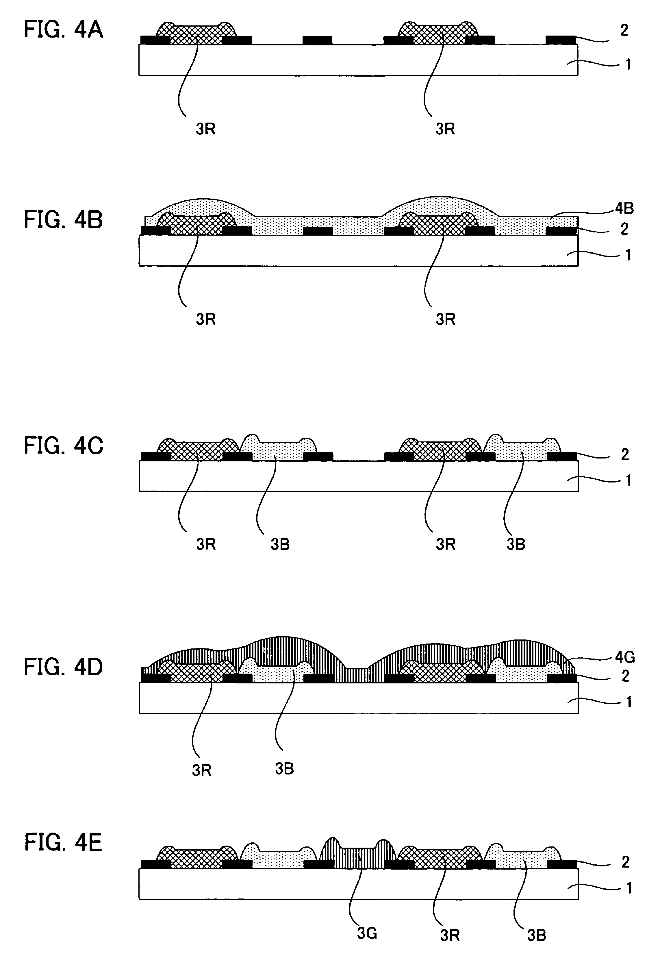
[0064]Hereinafter, with reference to the example and the comparative example, the present invention will be explained further specifically.


PUM

PropertyMeasurementUnit
thicknessaaaaaaaaaa
thicknessaaaaaaaaaa
thicknessaaaaaaaaaa

Abstract

A color filter including: a transparent substrate; a light shielding part formed on the transparent substrate and contains at least a light shielding material and a resin; and a colored layer formed in the opening part of the light shielding part on the transparent substrate to cover a part of the light shielding part. The light shielding part has: the width of the thick film region, 85% of more of the maximum film thickness of the light shielding part and disposed in the central part of the light shielding part, in a range of 30% to 60% of the light shielding part line width; and the width of each of the thin film regions, 50% or less of the maximum film thickness of the light shielding part and disposed on the both side parts of the light shielding part, in a range of 10% to 20% of the light shielding part line width.

Description

TECHNICAL FIELD[0001]The present invention relates to a high quality color filter with little risk of disturbing the liquid crystal alignment, or the like at the time of being used for a liquid crystal display apparatus.BACKGROUND ART[0002]At the time of forming a color filter used for a liquid crystal display apparatus, in general, a method of forming a light shielding part on a transparent substrate for forming a color filter, and forming a colored layer in the opening part thereof, or the like is used. As such a light shielding part, conventionally, a metal thin film with a metal such as a chromium vacuum deposited and processed by etching has been used. Recently, however, development of a resin-made light shielding part formed by coating a resin with a black pigment, or the like dispersed and patterning by the photolithography method, or the like has been promoted so as to realize its practical use. According to such a resin-made light shielding part, as compared with a light sh...

Claims


Application Information

Patent Timeline
Patent Type & Authority Patents(United States)
IPC IPC(8): G02B5/22G03F1/00G02B5/20G02F1/1335
CPCG02B5/201G02F1/133514G02B5/223G02F1/133512G02B5/20G02F1/1335
Inventor SUMINO, TOMONOBUFURUKAWA, SACHIETAWARAYA, SEIJIKATOH, CHIAKI
Owner DAI NIPPON PRINTING CO LTD
Why Eureka
Try Eureka