Disc drive suspension including load beam, load beam die set, and manufacturing method of load beam

a technology of disc drive and drive shaft, which is applied in the direction of manufacturing tools, integrated arm assemblies, shaping tools, etc., can solve the problems of uneven contact between the load beam and the flexure, and achieve the effect of improving the shape of the load beam

Pending Publication Date: 2021-12-09
NHK SPRING CO LTD
View PDF0 Cites 0 Cited by
  • Summary
  • Abstract
  • Description
  • Claims
  • Application Information

AI Technical Summary

Benefits of technology

[0010]The present application will present a disc drive suspension with improved load beam shape (especially, the shape of cross-section in the width direction), die set for the load beam, and manufacturing method of the load beam.

Problems solved by technology

A warped deformation in the proximity of the flange bending part of the load beam would cause malfunction.
For example, in the assembly state in which a flexure is disposed on the surface of the load beam, the gap between the load beam and the flexure may become uneven.
When the gap between the load beam and the flexure becomes uneven, they would contact to each other unevenly.
This would affect the gimbal movement of the flexure, and minute metal particles produced by the friction between the flexure and the load beam, and thus, it is undesirable.

Method used


Image

  • Disc drive suspension including load beam, load beam die set, and  manufacturing method of load beam
  • Disc drive suspension including load beam, load beam die set, and  manufacturing method of load beam
  • Disc drive suspension including load beam, load beam die set, and  manufacturing method of load beam

Examples


Embodiment Construction

[0031]Hereinafter, a disc drive suspension (hereinafter referred to as suspension) with a load beam of an embodiment will be explained with reference to FIGS. 1 to 10.

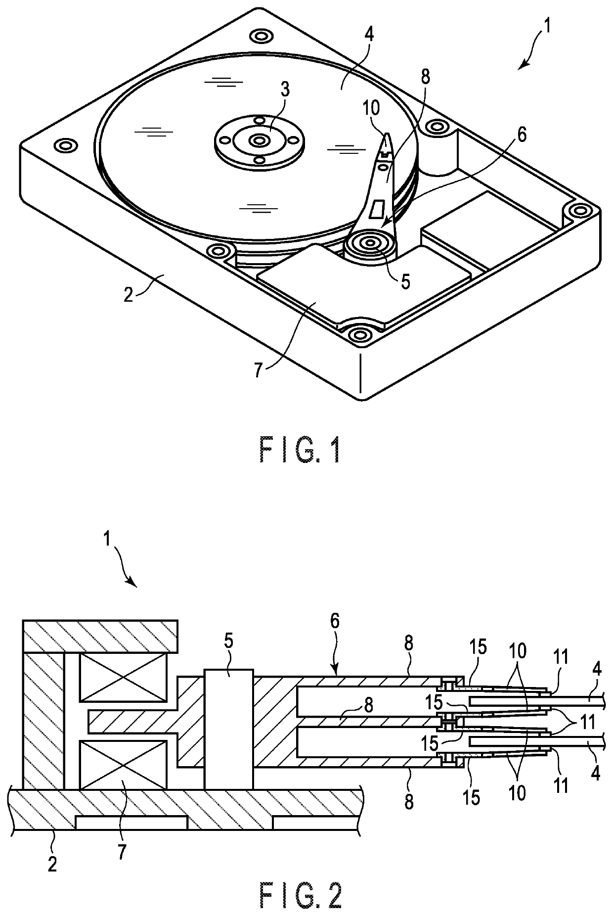
[0032]A disc drive (hard disc drive) 1 shown in FIG. 1 includes a case 2, disc (magnetic disc) 4 which rotates about a spindle 3, carriage 6 which spins about a pivot axis 5, and positioning motor 7 which spins the carriage 6. The case 2 is sealed with a lid which is not shown.

[0033]FIG. 2 is a schematic cross-sectional view of a part of the disc drive 1. An arm 8 is provided with the carriage 6. A suspension 10 is provided with the tip of the arm 8. A slider 11 of the magnetic head is provided with the proximity of the tip of the suspension 10. When the disc 4 rotates, air bearing is produced between the disc 4 and the slider 11. An element to record data to the disc 4 and an element to read data from the disc 4 are provided with the slider 11.

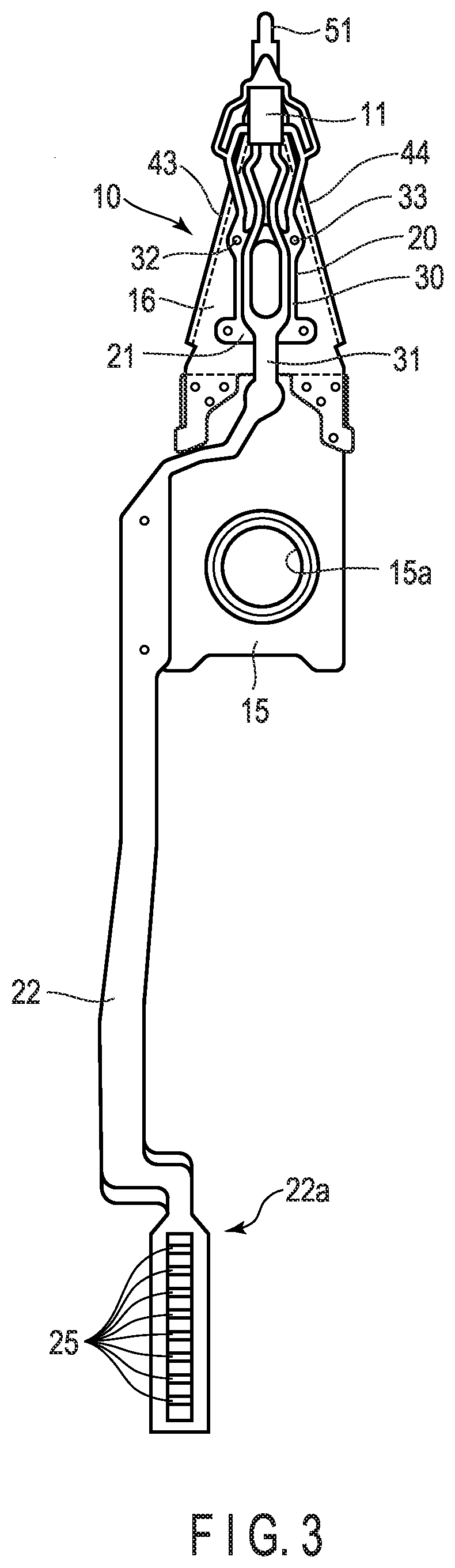
[0034]FIG. 3 is a plan view of an example of the suspension 10. The suspens...


PUM

PropertyMeasurementUnit
heightaaaaaaaaaa
heightaaaaaaaaaa
lengthaaaaaaaaaa

Abstract

A load beam includes a pair of flange bending parts including first bending parts, and a second bending part extending in a width direction. A first cross-section part extends in the width direction of the load beam passing through welding parts. The first cross-section part is warped up toward the flange parts. A second cross-section part extends in the width direction passing through a different position from that of the welding parts. The second cross-section part has a lesser height difference as compared to the first cross-section part. A die is used when bending the second bending part. The die includes a first relief part including a first inclined surface and a second relief part including a second inclined surface in both sides of the supporting surface.

Description

CROSS-REFERENCE TO RELATED APPLICATIONS[0001]This application is based upon and claims the benefit of priority from prior Japanese Patent Application No. 2020-097086, filed Jun. 3, 2020, the entire contents of which are incorporated herein by reference.BACKGROUND OF THE INVENTION1. Field of the Invention[0002]The present invention relates to a disc drive suspension including a load beam, die set used to bend a load beam, and manufacturing method of a load beam.2. Description of the Related Art[0003]Disc drives are used in information processing devices such as a personal computer. The disc drive includes a magnetic disc which rotates about a spindle and a carriage spinning about a pivot axis. A disc drive suspension is provided with an arm of the carriage.[0004]The disc drive suspension includes, for example, a base plate, load beam, and flexure arranged along the load beam. A slider is provided with a gimbal part formed in the proximity of the tip of the flexure. An element configu...

Claims


Application Information

Patent Timeline
Patent Type & Authority Applications(United States)
IPC IPC(8): G11B5/48
CPCG11B5/484G11B5/4833G11B33/04B21D5/0209B21D5/02B21D5/04B21D5/002B21D37/10
Inventor KUREBAYASHI, SOSUKEMITSUMORI, YOHEIIWAMOTO, NAOKI
Owner NHK SPRING CO LTD
Why Eureka
Try Eureka