
Fluid control device

a control device and flue gas technology, applied in valve housings, mechanical equipment, coatings, etc., can solve the problems of increased pressure loss and inability to control channels, and achieve the effects of reducing pressure variations, reducing pressure differences, and reducing manufacturing costs

Inactive Publication Date: 2006-05-11
FUJIKIN INC
View PDF6 Cites 11 Cited by
  • Summary
  • Abstract
  • Description
  • Claims
  • Application Information

AI Technical Summary

Benefits of technology

The present invention provides a fluid control device with a simplified structure and reduced pressure variations. The device has a center channel block and two side channel blocks with Y-shaped channels for supplying gas to the main gas channel and the vent gas channel. The shut-off valves are removably mounted on both channel blocks, making it easy to repair malfunctioning valves. The device body comprises three channel blocks, making it easier and less costly to fabricate and reducing dead space. The main gas channel and the vent gas channel can be made easily free of V-shaped or like angular portions, making the device suitable for high-flow rate applications.

Problems solved by technology

Furthermore, the device has problems in that it must be adapted for a changeover from one gas to another instantaneously with good stability without involving pressure variations and needs to be diminished in dead space.
The gas channel provided by the combination of a V-shaped channel and a three-port valve has many angular portions and a reduced cross section and is accordingly increased in pressure loss, hence the problem that the channel is unable to pass a fluid therethrough, for example, at a great flow rate in excess of about 100 liters / min.

Method used


Image

  • Fluid control device
  • Fluid control device
  • Fluid control device

Examples


Embodiment Construction

[0014] An embodiment of the invention will be described below with reference to the drawings. In the following description, the term “front” refers to the right-hand side of FIG. 1, and the term “rear” to the left-hand side of FIG. 1. The terms “left” and “right” are used for the device as it is seen from the front rearward. The terms “upper” and “lower” refer respectively to the upper and lower sides of FIG. 1.

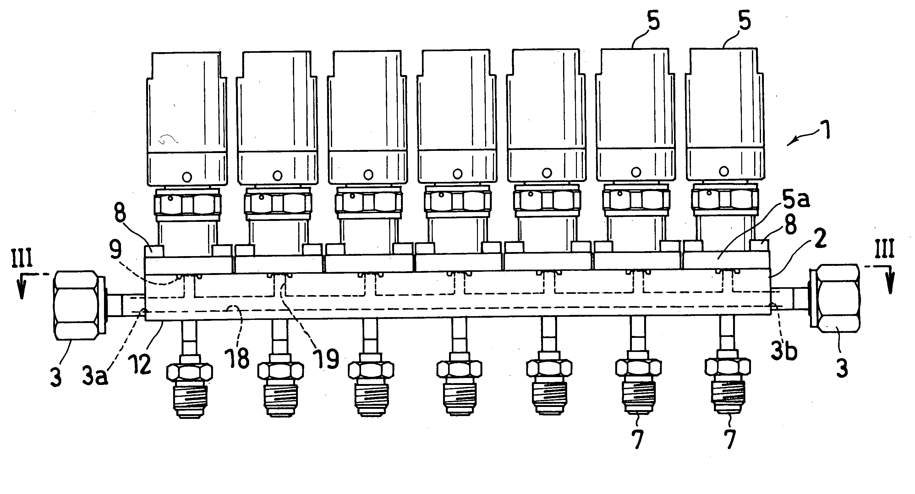
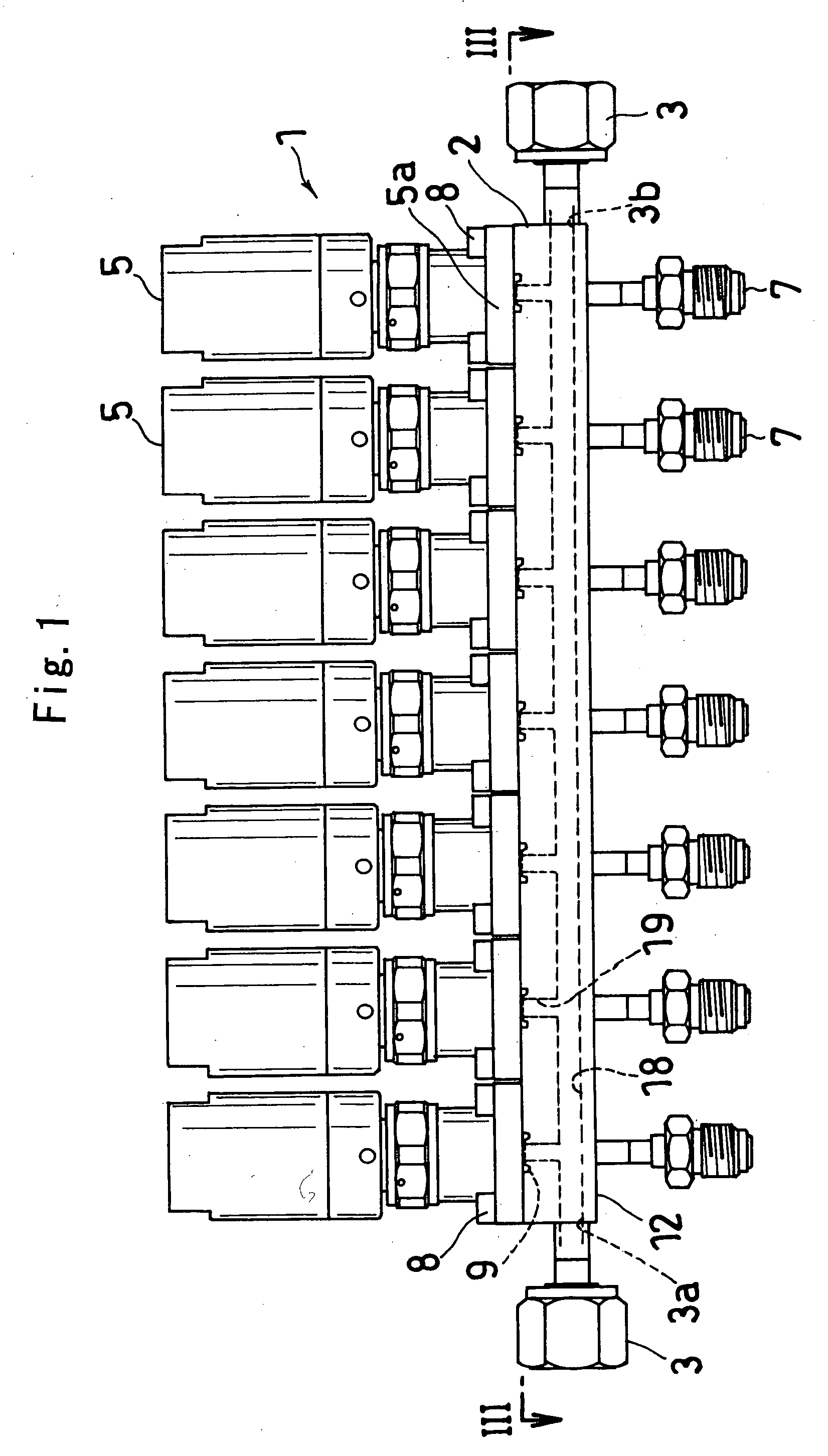
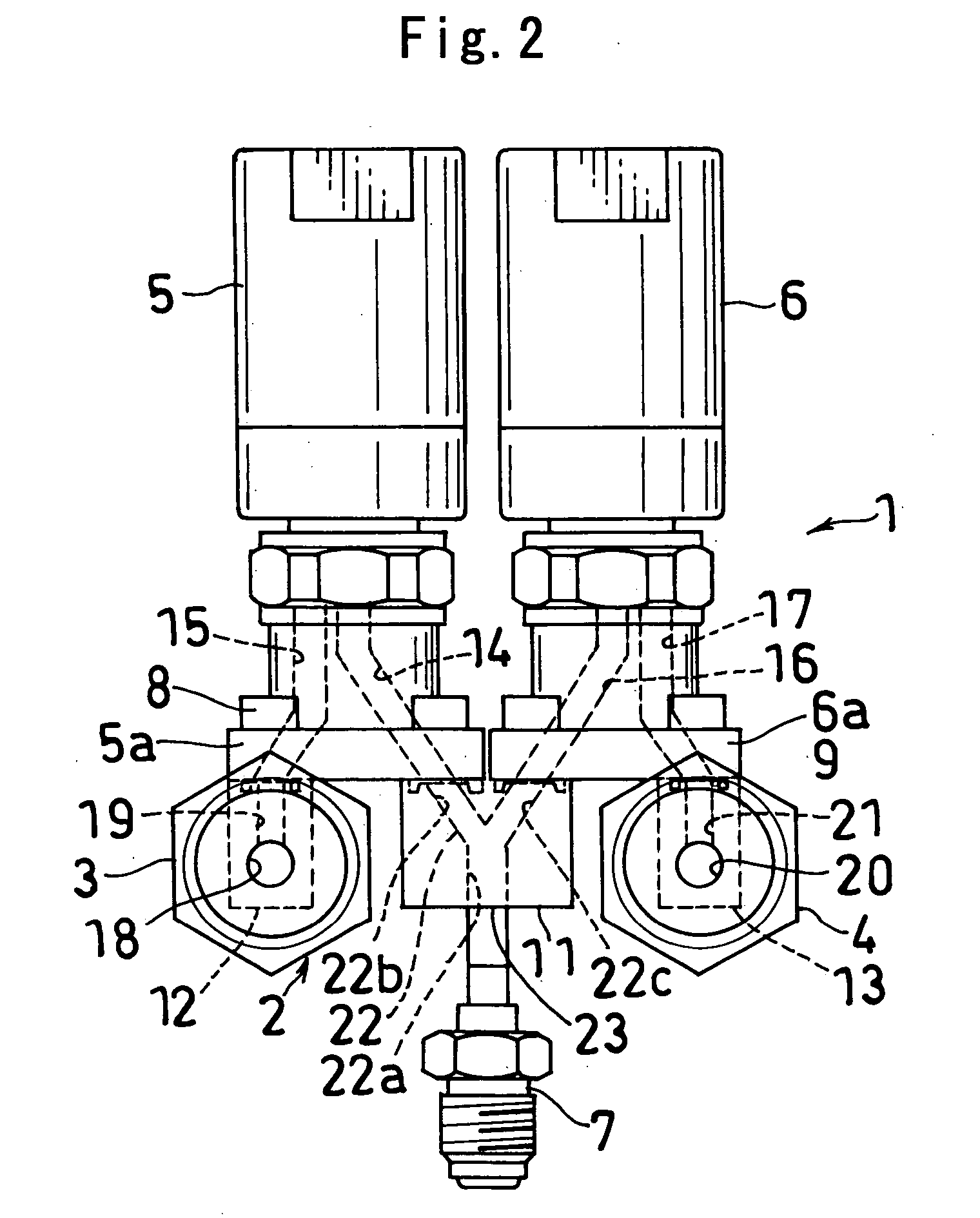
[0015] FIGS. 1 to 4 show an embodiment of fluid control device of the invention.

[0016] The fluid control device 1 of this embodiment is used, for example, for supplying different kinds of gases selectively upon a changeover for use in the MOCVD process. The device comprises a body 2, left-row inlet-outlet couplings 3 and right-row inlet-outlet couplings 4 provided at the front and rear ends of the body, left-row shut-off valves 5 and right-row shut-off valves 6 arranged in left and right two rows on the top of the body 2, the shut-off valves in each row being seven in numbe...


PUM

PropertyMeasurementUnit
flow rateaaaaaaaaaa
stabilityaaaaaaaaaa
pressure lossaaaaaaaaaa

Abstract

A body 2 comprises a center channel block 11 and side channel blocks 12, 13. Each of shut-off valves 5, 6 is removably mounted on both the center channel block and one of the side channel blocks. The center channel block has Y-shaped channels 22 identical in number with the number of the subgas inlets 23 and each comprising one common channel 22a and two branched channels 22b, 22c. The common channel 22a of the Y-shaped channel 22 has an opening serving as the subgas inlet 23 and the branched channels 22b, 22c of the Y-shaped channel 22 communicate with the inlet ports of the corresponding pair of shut-off valves 5, 6 to thereby provide the subgas inflow channels. The main gas channel 18 and the main channel communication passageways 19 are formed in one of the side channel blocks 12, and the vent gas channel 20 and the vent channel communication passageways 21 are formed on the other side channel block 13.

Description

TECHNICAL FIELD [0001] The present invention relates to fluid control devices, for example, for use in semiconductor processing apparatus for the purpose of selectively supplying different kinds of material gases to a processing chamber upon a changeover. BACKGROUND ART [0002]FIG. 5 shows a known fluid control device 31 for use in selectively supplying different kinds of material gases to a processing chamber upon a changeover. The device 31 comprises a rectangular parallelepipedal body 32, two main gas inlet-outlet members 33 arranged respectively at lengthwise opposite ends of the body 32, two vent gas inlet-outlet members (not shown) similarly arranged and each spaced apart from the corresponding member 33 widthwise of the body 32, a main gas channel 41 for holding the main gas inlet-outlet members 33 in communication with each other, a vent gas channel(not shown) for holding the vent gas inlet-outlet members in communication with each other, a plurality of subgas inlets 42 arran...

Claims


Application Information

Patent Timeline
Patent Type & Authority Applications(United States)
IPC IPC(8): H01L21/306C23C16/00F16K11/22F16K27/00
CPCF16K27/003F16K27/00
Inventor MOCHIZUKI, YASUNORIMAKINO, MEGUMUKOYOMOGI, MUTSUNORI
Owner FUJIKIN INC
Learn More