Thermal interface with a patterned structure

a patterned structure and thermal interface technology, applied in the direction of regenerative heat exchangers, indirect heat exchangers, lighting and heating apparatus, etc., can solve the problem of unfavorable thermal and mechanical properties, low effective viscosity, and limited effective conductivity above the percolation threshold, so as to achieve uniform and improve thermal and mechanical properties.

Inactive Publication Date: 2007-10-16
GLOBALFOUNDRIES INC
View PDF4 Cites 12 Cited by
  • Summary
  • Abstract
  • Description
  • Claims
  • Application Information

AI Technical Summary

Benefits of technology

[0014]The arrangement of the channels preferably further comprises substantially straight lines bisecting interior angles of channel-channel junctions and channel-edge junctions, wherein said substantially straight lines terminate on intersecting another substantially straight line. Advantage is gained through the introduction of the channels along the basic velocity gradients which reduces the pressure variations in the interface material.
[0016]Preferably, the first surface has an initial arrangement of channels which subdivide the first surface into a plurality of quadrangles, and further channels located at least approximately at local pressure maxima in the interface material. In the case of a thermal interface, such an arrangement more evenly distributes velocity gradients in the thermal interface material, resulting in more uniform and improved thermal and mechanical properties across the interface.

Problems solved by technology

Several problems are associated with known thermal interfaces.
First, it is found that there is an unexpected limit on the proximity of two surfaces when pressed together in a thermal interface.
Second, use of a TIM of low effective viscosity, due to a relatively low load of particles, entails the following problem.
The effective conductivity above the percolation threshold is, however, still limited to a relatively low value compared to the expected conductivity of the particles mixed with the matrix.
Third, non-uniform thermal properties are observed at known interfaces, which results in significant temperature gradients within the chip.
Maximum chip temperature is a parameter that determines thermal reliability of a chip and, therefore, temperature gradients are detrimental.
Fourth, when the chip package is thermally cycled, due to on-off cycles or varying processing loads, an interface warping between hot and cold positions is observed due to differences in thermal expansion coefficients between the components in the system.
This warping not only causes an undesirable TIM pumping effect which increases with a low effective viscosity TIM, but is also detrimental to the long term reliability of the interface due to voiding.

Method used


Image

  • Thermal interface with a patterned structure
  • Thermal interface with a patterned structure
  • Thermal interface with a patterned structure

Examples


Embodiment Construction

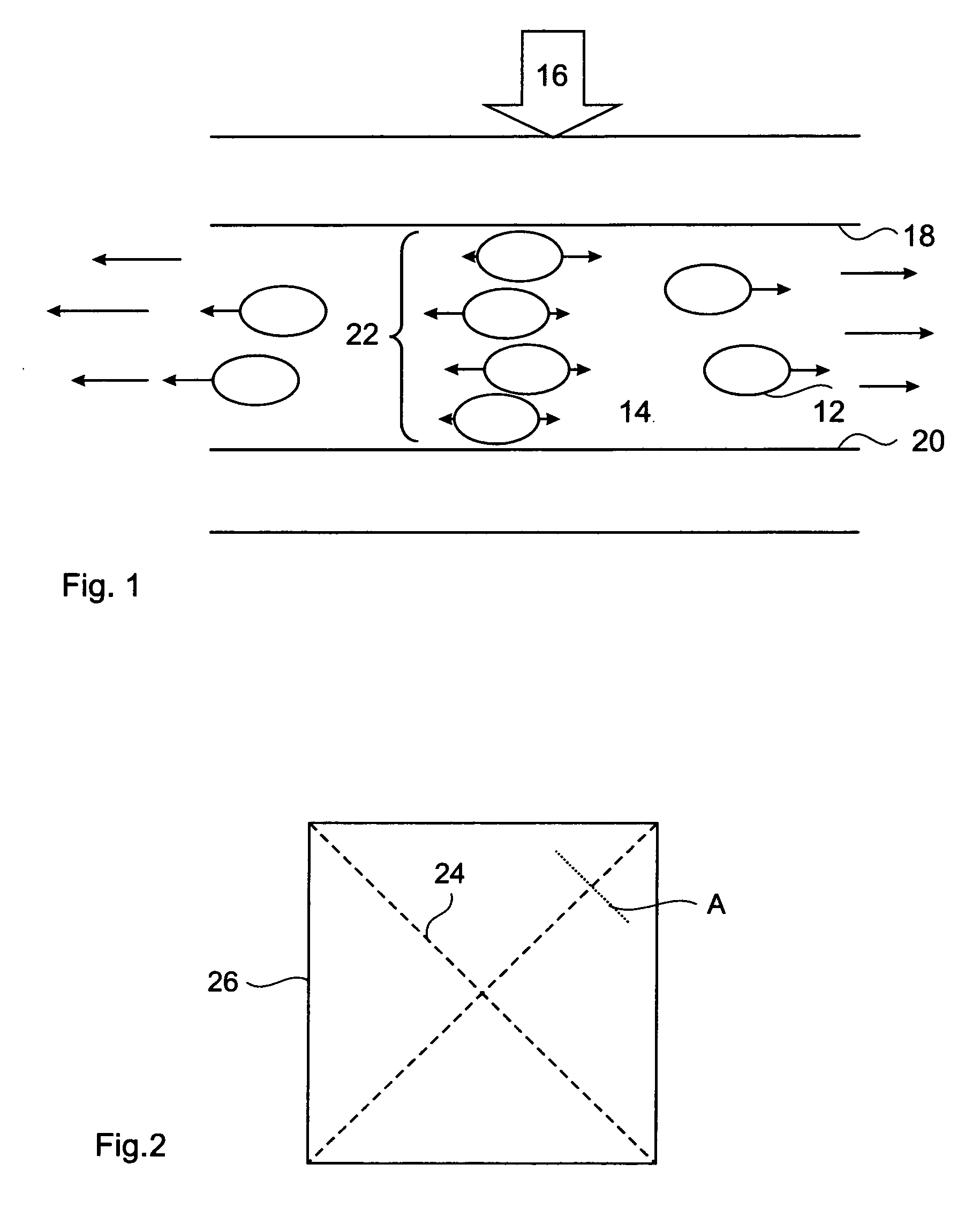
[0035]When a thermal interface is formed by pressing a flat face of the microprocessor chip and a flat face of the cooling device together, with a thermal interface material (TIM) between, the TIM flows in directions dependent upon the shape of the chip. For example, for a circular microprocessor chip, the net TIM flow speed is zero at the center of the circular face and increases with the radius. For a rectangular or quadratic chip, the TIM flow similarly increases with the distance from the center and additionally flows outward from the center until the edges of the chip are reached. Further, velocity gradients in the TIM develop due to pressure variations which are primarily a function of the distance the TIM must flow to reach the perimeter of the chip.

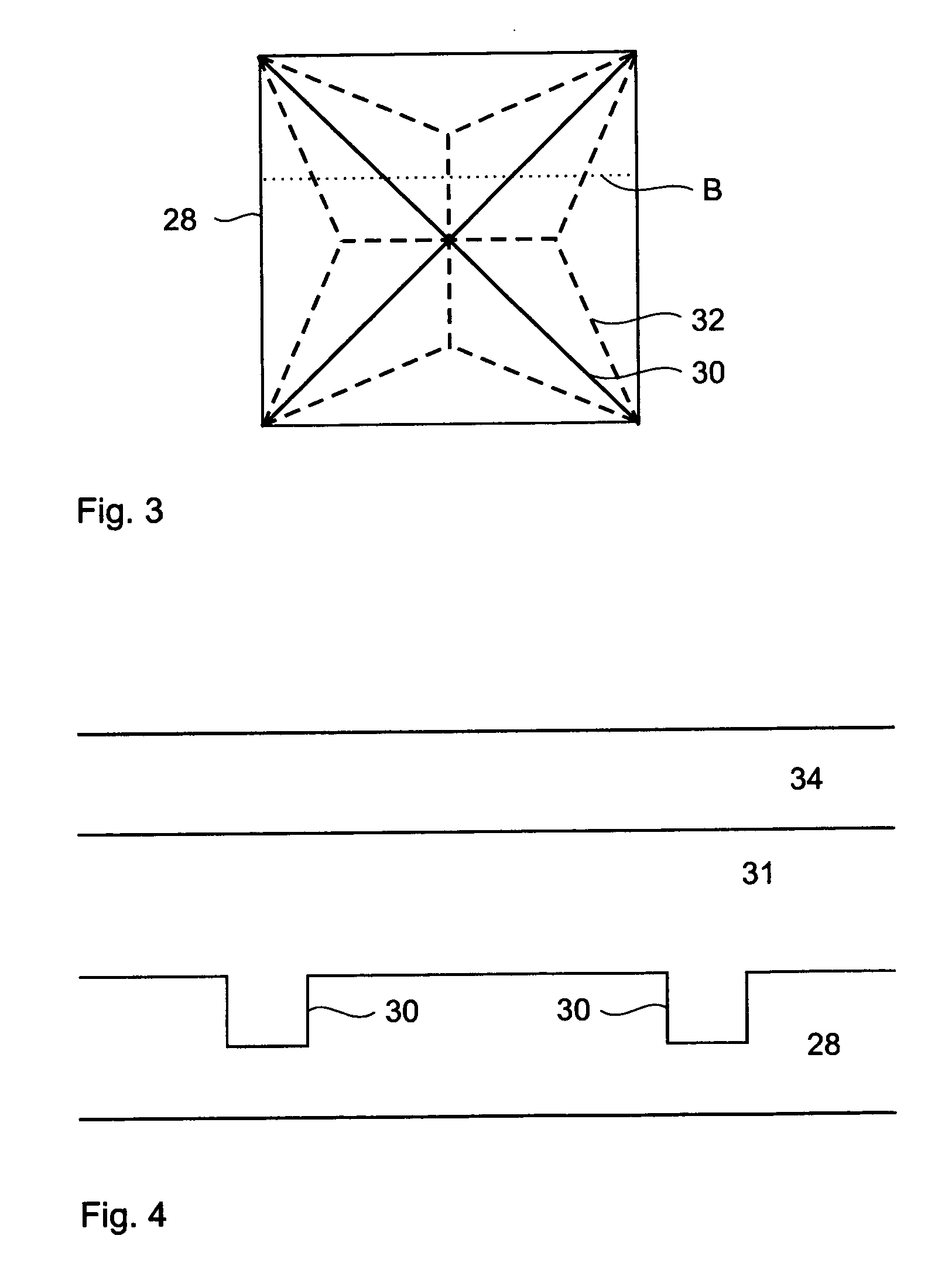
[0036]For a thermal interface on a quadrangular or rectangular plate, the velocity gradients are located along lines connecting diagonally opposite corners because the largest pressure drop occurs where the TIM must flow the large...


PUM

PropertyMeasurementUnit
depthaaaaaaaaaa
widthaaaaaaaaaa
depthaaaaaaaaaa

Abstract

An interface is formed by pressing a patterned first surface and a second surface together, with a particle-loaded interface material in between. The first surface is fabricated with a pattern of channels designed to redistribute the velocity gradients that occur in the interface material during interface formation in order to control the arrangement, orientation and concentration of particles at the end of the interface formation. The concept finds application in thermal interfaces and controlled placement of nano and micro particles and biological molecules.

Description

FIELD OF THE INVENTION [0001]This invention relates to an interface with a patterned structure and particularly relates to thermal interfaces between microprocessor chips and cooling devices.BACKGROUND OF THE INVENTION [0002]In the field of microelectronic chip packages, the interface between the chip package and a cooling device is a dominant thermal resistance. Techniques to improve thermal conduction at this interface are important features in thermal management solutions, along with the traditional techniques of reducing the chip package internal and external thermal resistance. Thermal interfaces are typically formed by pressing a flat surface of the microprocessor chip and a flat surface of the cooling device together, with a thermal interface material (TIM) in between that is forced to flow into cavities or non-uniformities of the surfaces. A TIM is generally a particle-loaded viscous medium, which is also known in the art as a paste or grease or adhesive.[0003]In U.S. Pat. N...

Claims


Application Information

Patent Timeline
Patent Type & Authority Patents(United States)
IPC IPC(8): H01L23/10F28D17/04H01L21/00
CPCH01L23/3733H01L23/3737H01L23/42H01L24/83H01L24/32H01L2224/73253H01L2924/01057H01L24/29H01L2224/8385H01L2224/2929H01L2224/293H01L2224/32245H01L2224/83365H01L2224/83385
Inventor BRUNSCHWILER, THOMAS J.KLOTER, URSLINDERMAN, RYAN JOESPHMICHEL, BRUNOROTHUIZEN, HUGO E.
Owner GLOBALFOUNDRIES INC
Why Eureka
Try Eureka