Vehicular lamp

Inactive Publication Date: 2010-11-18
KOITO MFG CO LTD
View PDF18 Cites 23 Cited by
  • Summary
  • Abstract
  • Description
  • Claims
  • Application Information

AI Technical Summary

Benefits of technology

[0007]A structure in which an FPC is mounted with a plurality of LEDs as in Patent Document 1 could use a structure in which the FPC is adhesively fixed to a heat sink using an adhesive with excellent thermal conductivity as in Patent Document 2 to increase the heat radiation performance of heat generated by the LEDs. However, if adhesive bubbles are created when adhering the FPC to the heat sink, these bubbles may lower thermal conductivity between the FPC and the heat sink, thus lowering the heat radiation performance of the light-emitting element. To ensure that such bubbles are not created, a structure has been proposed in the past that first a

Problems solved by technology

However, if adhesive bubbles are created when adhering the FPC to the heat sink, these bubbles may lower thermal conductivity between the FPC and the heat sink, thus lowering the heat radiation performance of the light-emitting element.
In this proposed heat radiation structure, a sub-substrate is needed in addition to the FPC and the heat sink for releasi

Method used


Image

  • Vehicular lamp
  • Vehicular lamp
  • Vehicular lamp

Examples


first embodiment

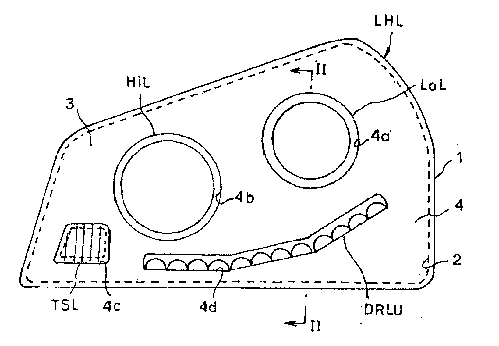
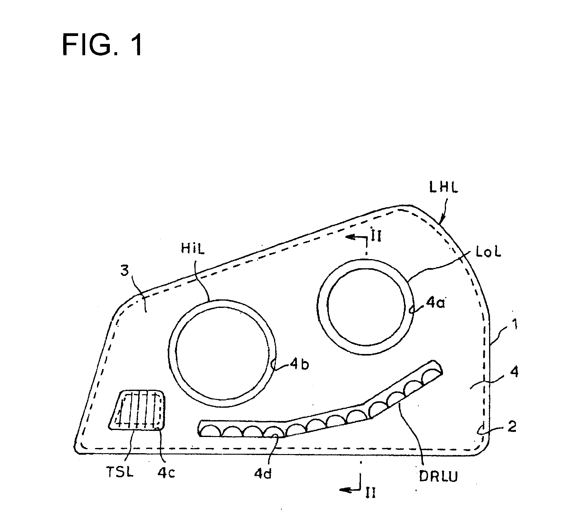
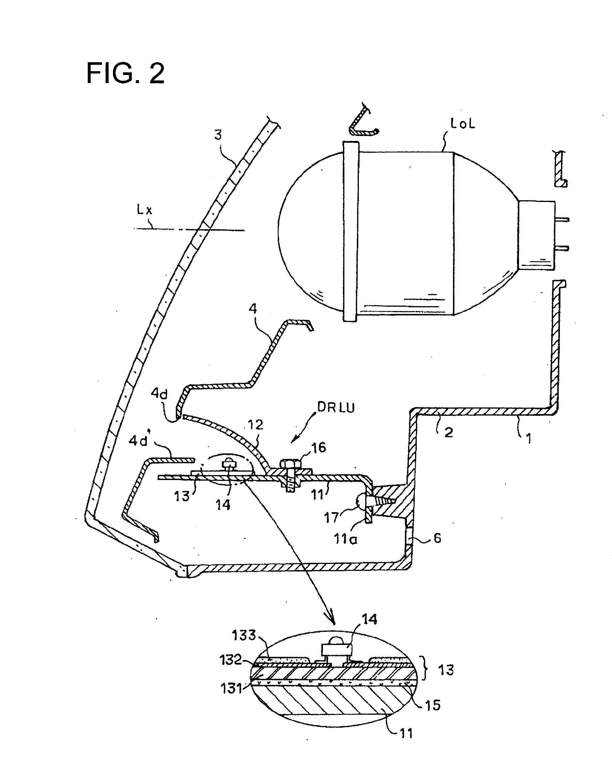
[0025]Hereinafter, embodiments of the present invention will be described with reference to the accompanying drawings. FIG. 1 is a schematic frontal view of an embodiment of the present invention applied to a left headlamp LHL among headlamps provided on the right and left sides of a front body portion of an automobile. FIG. 2 is an enlarged cross-sectional view taken along a line II-II in FIG. 1. A lamp housing 1 is formed from a container-like lamp body 2 and a transparent front cover 3. A low-beam lamp LoL, a high-beam lamp HiL, and a turning signal lamp TSL are provided aligned inside the lamp housing 1, with the low-beam lamp LoL on the right side and the high-beam lamp HiL and the turning signal lamp TSL on the left side as viewed from the front. The low-beam lamp LoL and the high-beam lamp HiL may be formed from any type of lamp. In this embodiment, for example, the low-beam lamp LoL and the high-beam lamp HiL are formed from projector type lamps that use a discharge bulb or ...

second embodiment

[0042]FIG. 5 is a schematic perspective view of a DRL unit DRLU2 according to a second embodiment. Here, a base substrate 11A is formed with a planar shape having a narrow arc that curves along the curve of the front edge of the extension 4 or the lamp housing 1. The base substrate 11A is fixed to the rear inner surface of the lamp body 2 (similar to the embodiment shown in FIG. 2) by a reverse L-shaped support tab 11a that is provided at a plurality of locations in the length direction of the base substrate 11A. An FPC 13A is formed with a similar narrow arc corresponding to the base substrate 11A, and a plurality of LEDs 14 is mounted in the length direction of the FPC 13A. One base substrate 11A is used in the second embodiment, and this FPC 13A is adhered and fixed to a flat portion that accounts for almost the entire top surface of the base substrate 11A, with the plurality of LEDs 14 mounted on the FPC 13A. Specifically, four LEDs 14 are mounted so as to be similarly positione...

third embodiment

[0045]FIG. 6 is a cross-sectional view similar to FIG. 2 of a DRL unit DRLU3 according to a third embodiment. FIG. 7 is a schematic perspective view. Three base substrates 11B are each formed into an L-shape with the front edge portions formed bending vertically upward. A front edge portion 11b of each base substrate 11B is formed as a flat portion that is flat in the vertical direction, and the front edge portion 11b is provided inside the lamp housing 1 so as to be positioned behind the opening window 4d of the extension 4. In addition, a horizontally oriented rear edge portion 11c is fixed by a screw 19 (see FIG. 6) on a lower edge portion 4e that is bent toward the rear of the extension 4, and thereby integrated with the extension 4.

[0046]An FPC 13B, similar to the first embodiment, extends over three base substrates 11B. A front edge portion 11b of the base substrate 11B is vertically oriented. Using an adhesive, the FPC 13B is adhered to and integrated with the front edge port...


PUM


Abstract

A vehicular lamp including a light source unit including a light-emitting element inside a lamp housing; a planar wiring member on which the light-emitting element is mounted; and a support substrate having a flat portion that supports the planar wiring member. The support substrate is formed from a plate having high thermal conductivity, the planar wiring member is fixed to the flat portion of the support substrate, and a portion of the support substrate is fixedly supported inside the lamp housing.

Description

BACKGROUND OF INVENTION[0001]1. Field of the Invention[0002]The present invention relates to a vehicular lamp having a light-emitting element as a light source. More specifically, the present invention relates to a vehicular lamp having a constitution in which the light-emitting element is mounted on a flexible circuit board and installed inside a lamp housing.[0003]2. Related Art[0004]Lamps having a light-emitting element such as a light-emitting diode (LED) or the like as a light source have been proposed as vehicular lamps in recent years. In this type of lamp, when a plurality of LEDs is provided for obtaining a required light intensity in the lamp, a configuration may be used in which the plurality of LEDs is mounted on a flexible printed circuit board (FPC) and the FPC is installed inside a lamp housing as in Patent Document 1. A heat radiation structure is also required for releasing heat generated by the LEDs in order to improve the light-emitting characteristic of the LEDs....

Claims


Application Information

Patent Timeline
IPC IPC(8): B60Q1/00F21V7/00F21W107/10
CPCB60Q1/0047B60Q1/2696B60Q1/28B60Q2400/30F21Y2101/02F21S48/1154F21S48/1159F21S48/25F21V17/12F21S48/1104F21Y2115/10F21S41/19F21S41/143F21S43/50F21S41/151F21S41/148B60Q2900/40F21V17/00F21V29/00
Inventor TSUKAMOTO, HIRONORI
Owner KOITO MFG CO LTD
Why Eureka
Try Eureka