Switching Unit or Switching Gear

Inactive Publication Date: 2015-04-16
HITACHI IND EQUIP SYST CO LTD
View PDF5 Cites 7 Cited by
  • Summary
  • Abstract
  • Description
  • Claims
  • Application Information

AI Technical Summary

Benefits of technology

[0009]According to the present invention, it is possible to provide a switching unit or switching

Problems solved by technology

Recently, in urban areas there has been a problem that power consumption concentrates in certain regions and construction of distributing substatio

Method used


Image

  • Switching Unit or Switching Gear
  • Switching Unit or Switching Gear
  • Switching Unit or Switching Gear

Examples


first embodiment

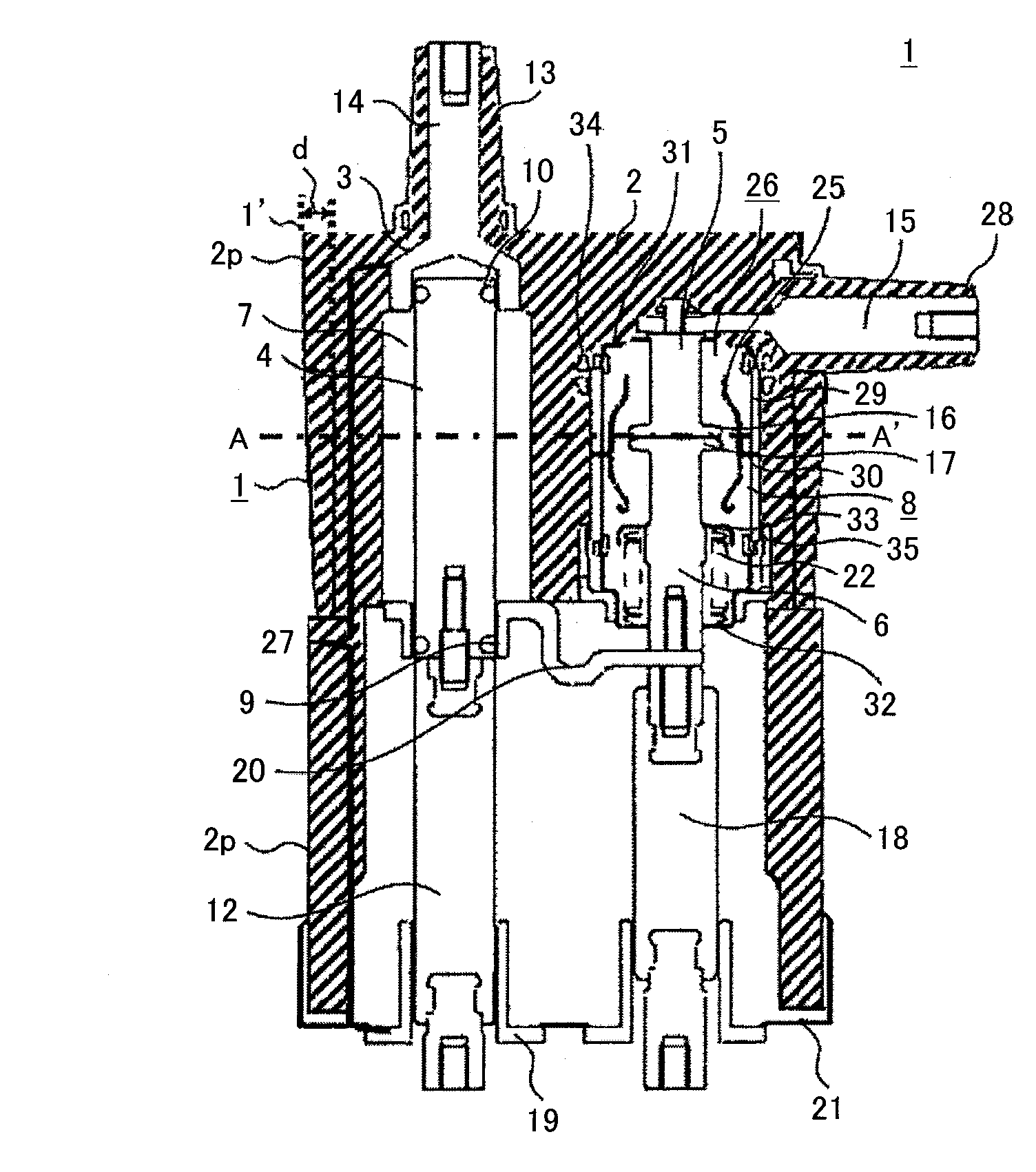
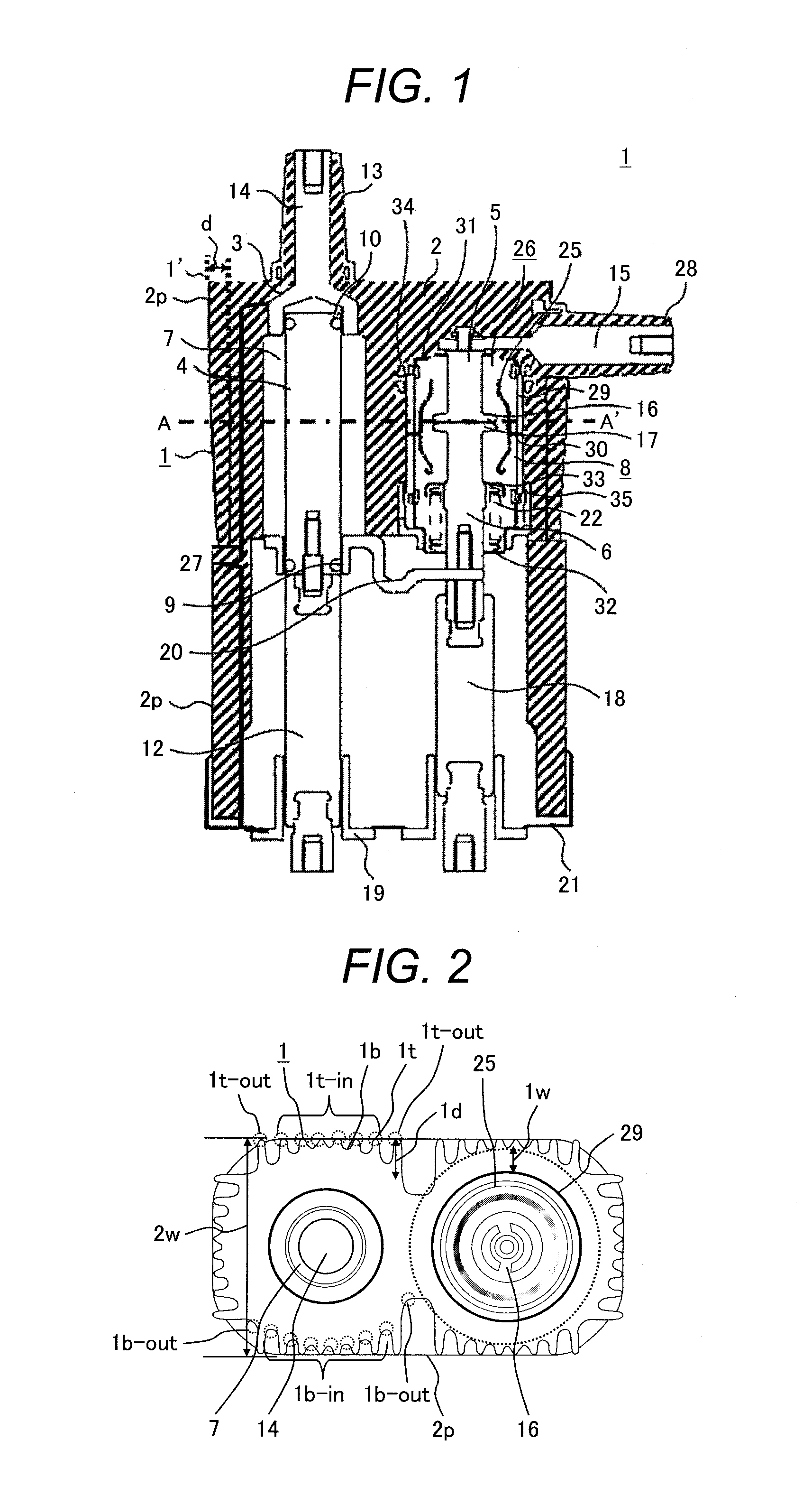
[0019]Next, the first embodiment will be described referring to FIGS. 1 and 2.

[0020]As shown in FIG. 1, the switching unit according to this embodiment mainly includes a grounded metal case 21, insulating resin 2 of epoxy, etc. connected to the metal case 21, a vacuum valve 26 and a grounding disconnection part 27 which are integrally cast with the insulating resin 2, a bushing 13 for a bus, and a bushing 28 for a cable.

[0021]The vacuum valve 26 has, in a vacuum container 8 constituted by connecting a fixed side ceramics insulating cylinder 29, movable side ceramics insulating cylinder 30, fixed side end plate 31 and movable side end plate 32: a fixed side electrode 16; a movable side electrode 17; a fixed side conductor 5 connected to the fixed side electrode 16; a movable side conductor 6 connected to the movable side electrode 16, a movable side conductor 6 connected to the movable side electrode 17; and an arc shield 25 for protecting the ceramic insulating cylinders 29 and 30 f...

second embodiment

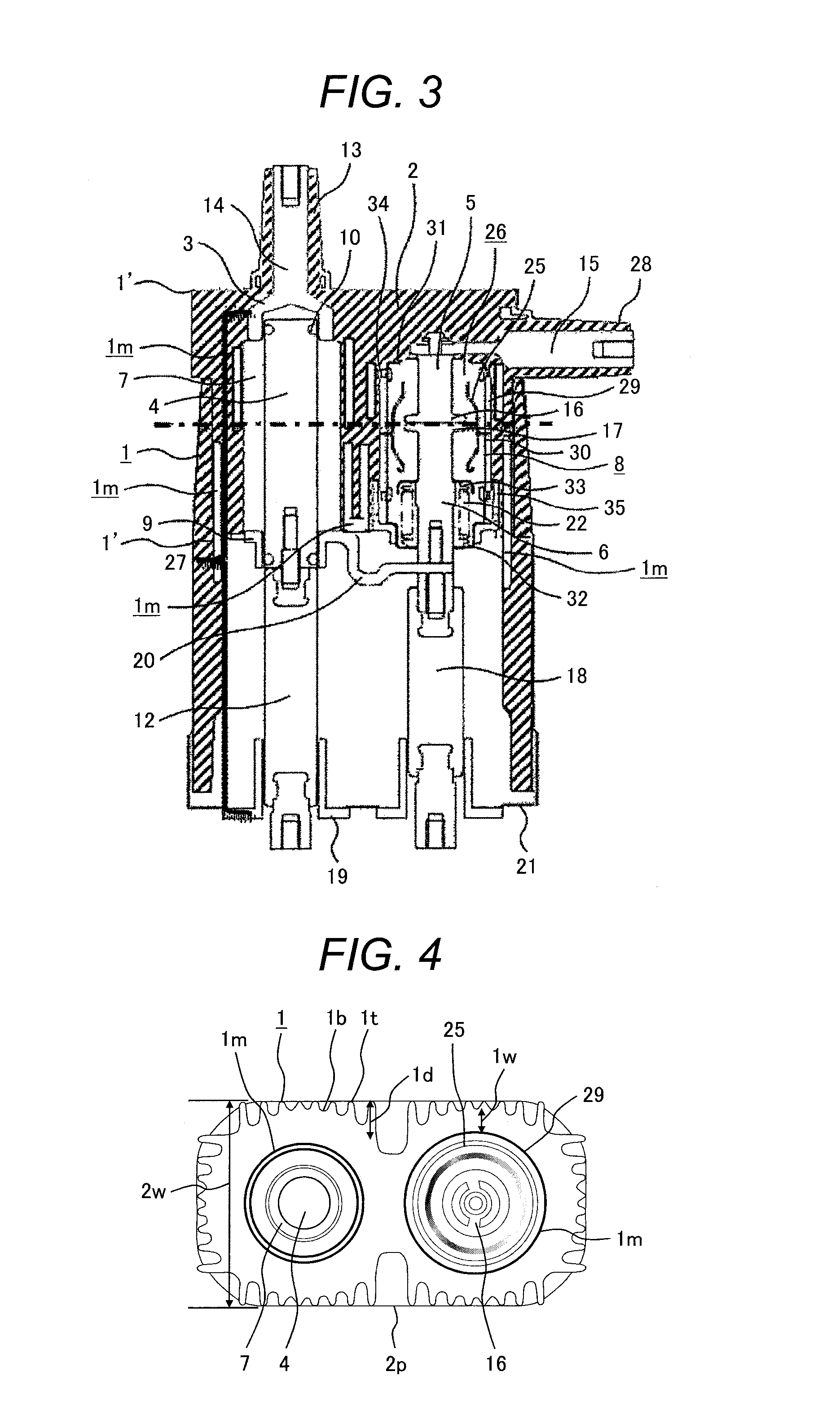
[0046]The second embodiment will be described referring to FIGS. 3 and 4. Descriptions of the same elements as in the first embodiment will be omitted.

[0047]As shown in FIGS. 3 and 4, in this embodiment, metal radiating plates 1m located inside the insulating resin 2 function as both an insulating shield and a heat radiating member simultaneously. Also the metal radiating plates 1m are connected and fixed to the bus bushing 13, cable bushing 28, and middle fixed electrode 9 which are heat accumulation spots, and the heat is radiated to the resin layer, in which the resin radiating fin height is large in (largest height 1′) in a resin layer high-temperature area and is smaller in remoter areas than the area. The height of the resin radiating fins 1 is the largest around the radiating plate 1m nearest to the insulating resin 2 surface among the radiating plates 1m and the height is smaller in remoter areas from around the radiating plate 1m nearest to the insulating resin 2 surface. T...

third embodiment

[0051]The third embodiment will be described referring to FIGS. 5 to 7. In this embodiment as well, descriptions of the same elements as in the above embodiments will be omitted.

[0052]In the first and second embodiments, the tips of the resin radiating fins 1 form two pairs of planes: a pair of planes facing each other with the aerial grounding disconnection part 27 or the vacuum valve 26 between them and a pair of planes facing each other with the aerial grounding disconnection part 27 and the vacuum valve 26 between them; on the other hand, in this embodiment, as shown in the sectional view of FIG. 5, when the whole outer surface of the integrally cast switch is formed with cooling fins thereon, in order to minimize the number of casting mold parts, resin radiating fins are not provided on both the lateral sides, and the resin distance 1W between the bottoms 1b of the resin radiating fins on the front and rear sides and the periphery of the vacuum container 8 is kept constant.

[005...


PUM


Abstract

An object is to provide a switching unit or switching gear which enhances heat radiation performance and eliminates the need for an increase in unit size. In order to solve this problem the switching unit includes a switch and insulating resin located in a way to cover the periphery of the switch, in which the switch includes a fixed electrode, a movable electrode facing the fixed electrode and moving in an axial direction to contact or leave the fixed electrode, a bus side conductor connected to one of the electrodes and connected to a bus, and a load side conductor connected to the other electrode and connected to the load. The insulating resin has fins formed in a circumferential direction on the outer surface of the insulating resin and the distance between the periphery of the switch and the bottoms of the fins is almost constant in the circumferential direction.

Description

TECHNICAL FIELD[0001]The present invention relates to switching units or switching gear and more particularly to cooling of a switching unit or switching gear which is solid-insulated with insulating resin.BACKGROUND ART[0002]Switching gear is installed as a power reception / distribution device in a power system to receive generated power from a power plant and distribute it to a load. A switching unit is installed in switching gear and is a key part of the switching gear which houses a switch.[0003]Recently, in urban areas there has been a problem that power consumption concentrates in certain regions and construction of distributing substations in response to the growing demand for power consumption is difficult and there is shortage of space for installation of power distributing pipes. In addition, the demand for higher operating rates of supply facilities is growing. In order to respond to the demand, studies have been conducted on the construction of efficient power supply faci...

Claims


Application Information

Patent Timeline
IPC IPC(8): H01H33/662H01H33/66H01H33/666
CPCH01H33/66207H01H33/6661H01H33/6606H01H2033/6613H01H2033/6623H01H33/662H01H2033/66215
Inventor YAMAZAKI, MIKIUTSUMI, TOMOAKIYABU, MASATOMORITA, AYUMU
Owner HITACHI IND EQUIP SYST CO LTD
Why Eureka
Try Eureka