
Fan motor apparatus having improved heat-radiation performance

Inactive Publication Date: 2015-04-23
DONGYANG MECHANTRONICS CORP
View PDF12 Cites 3 Cited by
  • Summary
  • Abstract
  • Description
  • Claims
  • Application Information

AI Technical Summary

Benefits of technology

The present invention is a fan motor apparatus that improves heat-radiation performance by enhancing the radiating fin structure of the motor unit to efficiently cool the heat generated in electronic devices located inside. The apparatus includes a stator with an electronic device, a central shaft, a rotator, a heat-radiation fin portion, and a cooling fin combined air flow guide. The heat-radiation fin portion generates wind towards the stator when the rotator rotates, while the cooling fin combined air flow guide increases the heat exchange area between the air generated by the heat-radiation fin portion and the air inside the rotator, and induces air from the exterior of the stator towards the central shaft. The technical effect of the invention is improved heat-radiation performance, leading to efficient cooling of electronic devices and reduced likelihood of malfunctions or damage.

Problems solved by technology

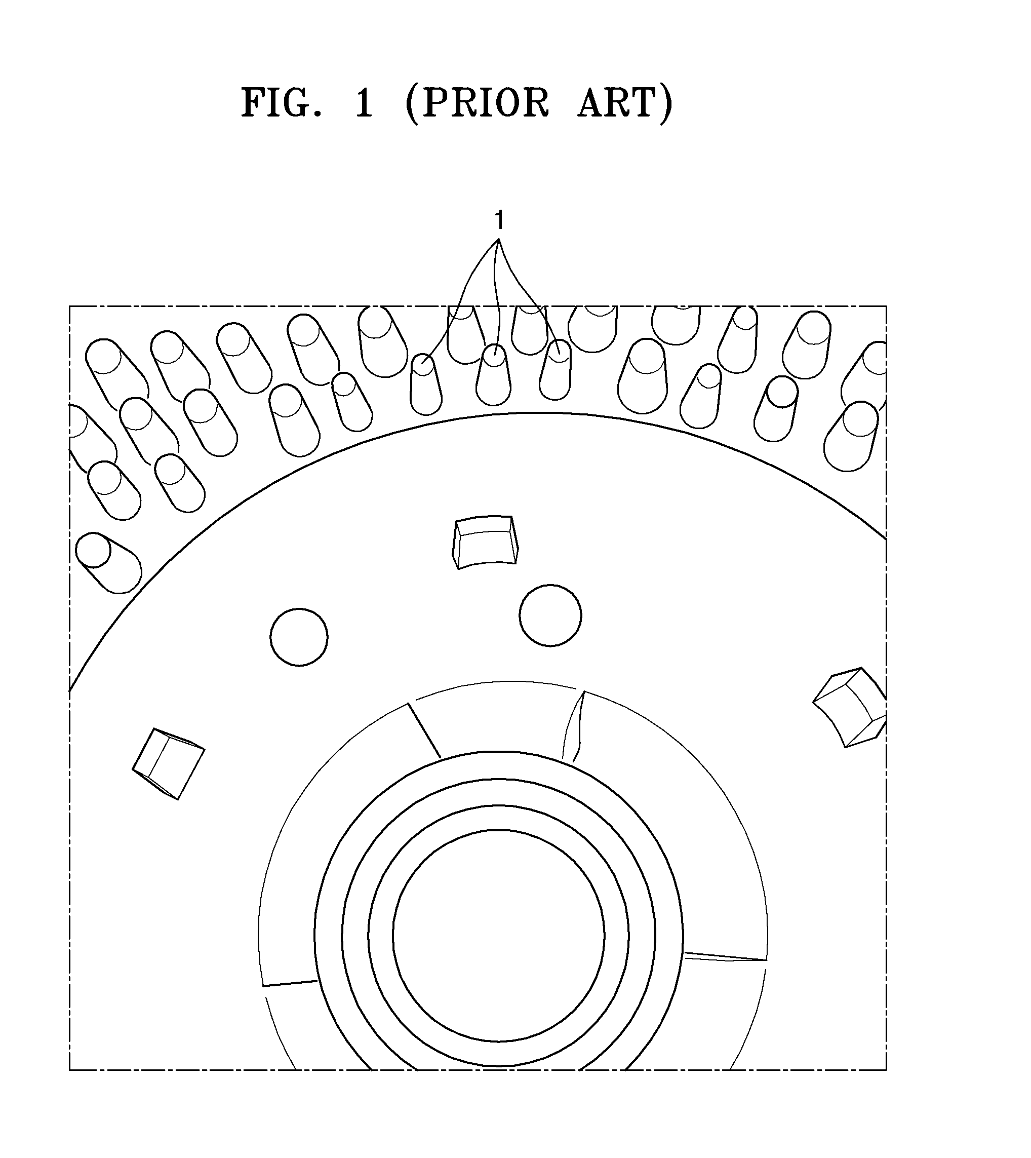
However, the conventional heat radiating fins 1 only widen the heat exchange area and are hard to directly introduce the outside air into a motor.

Method used


Image

  • Fan motor apparatus having improved heat-radiation performance
  • Fan motor apparatus having improved heat-radiation performance
  • Fan motor apparatus having improved heat-radiation performance

Examples


Embodiment Construction

[0021]Reference will now be made in detail to embodiments, examples of which are illustrated in the accompanying drawings, wherein like reference numerals refer to like elements throughout. In this regard, the present embodiments may have different forms and should not be construed as being limited to the descriptions set forth herein. Accordingly, the embodiments are merely described below, by referring to the figures, to explain aspects of the present description.

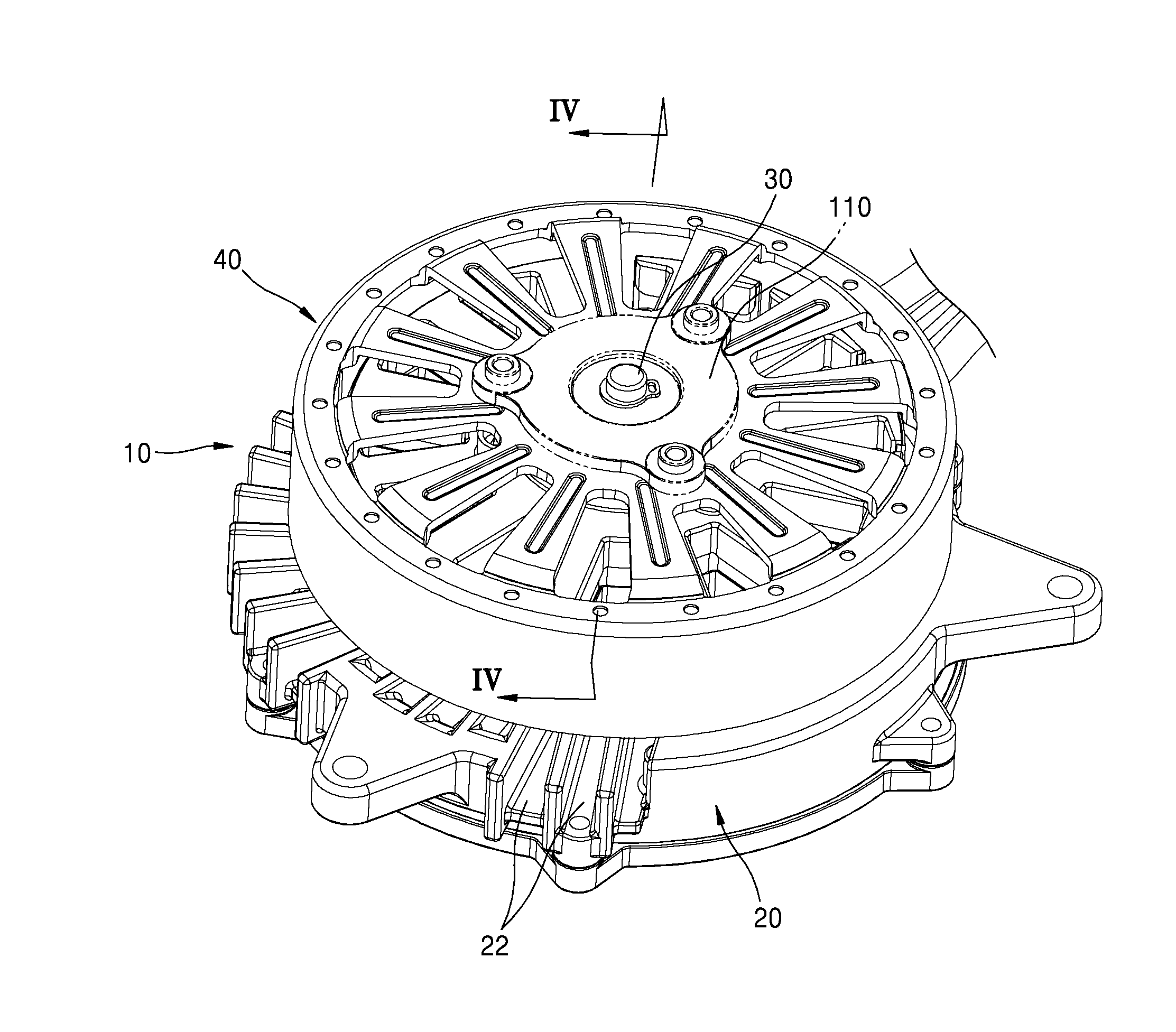
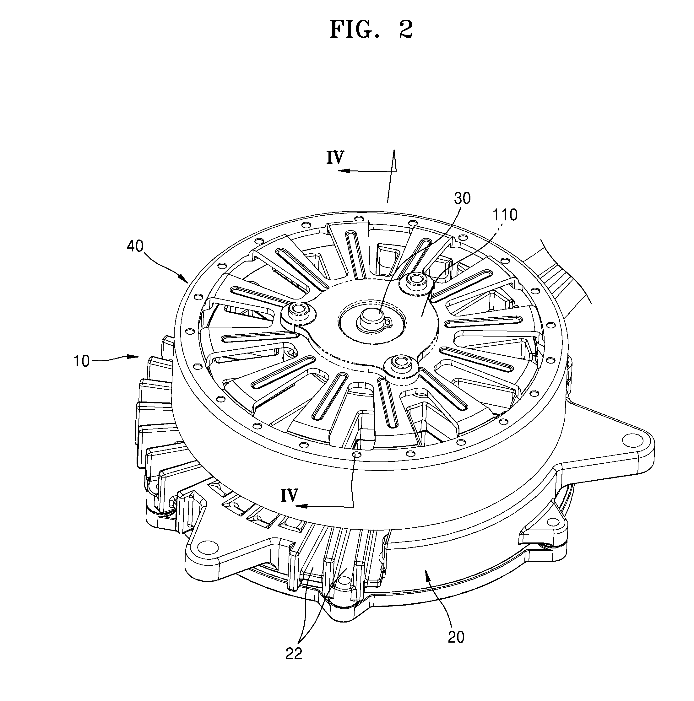
[0022]FIG. 2 is a schematic perspective view of a fan motor apparatus 10 according to an exemplary embodiment of the invention. FIG. 3 is a perspective view showing a structure of a stator 20 included in the fan motor apparatus 10 shown in FIG. 2. FIG. 4 is a sectional view taken along line IV-IV shown in FIG. 2.

[0023]Referring to FIGS. 2 through 4, the fan motor apparatus 10 having an improved heat-radiation performance (hereinafter, referred to as “a fan motor apparatus 10”) includes the stator 20, a central shaft 30, a...


PUM


Abstract

A fan motor apparatus having an improved heat-radiation performance includes a stator including an electronic device; a central shaft which is fixed onto the upper surface of the stator; a rotator mounted rotatably with the respect to the stator by being rotatably coupled to the central shaft; a heat-radiating fin portion provided on an inner surface of the rotator to generate wind toward the stator when the rotator rotates; and an cooling fin combined air flow guide formed on a surface of the stator to increase a heat exchange area for a heat exchange between the air generated by the heat-radiation fin portion and the air inside the stator; and at the same time guide the air from the exterior of the stator toward the central shaft so that the air is introduced into the rotator via a lower surface of the rotator.

Description

RELATED APPLICATIONS[0001]This application claims the benefit of Korean Patent Application No. 10-2013-0126748, filed on Oct. 23, 2013, in the Korean Intellectual Property Office, the disclosure of which is incorporated herein in its entirety by reference.BACKGROUND[0002]1. Field[0003]One or more embodiments of the present invention relate to a fan motor apparatus.[0004]2. Description of the Related Art[0005]In general, a fan motor apparatus is provided to cool a component that generates a heat, such as car radiators, freezers, refrigerators, and air-conditioning equipment.[0006]A general structure of the fan motor apparatus includes a motor unit generating a rotational driving force, and a blowing fan that is coupled to the motor unit and blows air.[0007]An example of such a fan motor apparatus is disclosed in Korea Utility Model Publication No. 2008-0000346.[0008]In general, the motor unit of the fan motor apparatus includes a rotator and a stator. An electronic circuit that is a ...

Claims


Application Information

Patent Timeline
IPC IPC(8): H02K5/18H02K9/00
CPCH02K9/00H02K5/18H02K9/06F04D29/5806F04D25/08F04D29/541F04D29/601F05D2210/12F05D2260/60Y10S415/00Y10S417/00
Inventor KIM, SANG GIL
Owner DONGYANG MECHANTRONICS CORP
Learn More