In-vehicle motor-driven compressor

a motor-driven compressor and compressor technology, applied in the direction of positive displacement liquid engines, pumps, machines/engines, etc., can solve the problems of reducing the damping effect and likely trapped heat inside, and achieve the effect of superior heat radiation performance and damping

Active Publication Date: 2021-03-25
TOYOTA IND CORP
View PDF3 Cites 1 Cited by
  • Summary
  • Abstract
  • Description
  • Claims
  • Application Information

AI Technical Summary

Benefits of technology

[0004]Accordingly, it is an objective of the present disclosure to provide an in-vehicle motor-driven compressor having a filter circuit with superior heat radiation performance and damping effect.

Problems solved by technology

In a case where a choke coil is entirely covered with a conductor, the heat is likely to be trapped inside.
On the other hand, if a choke coil is designed to have a section not covered with a conductor in order to enhance the heat radiation performance, induced current would not flow readily in that section, reducing the damping effect.

Method used


Image

  • In-vehicle motor-driven compressor
  • In-vehicle motor-driven compressor
  • In-vehicle motor-driven compressor

Examples


first embodiment

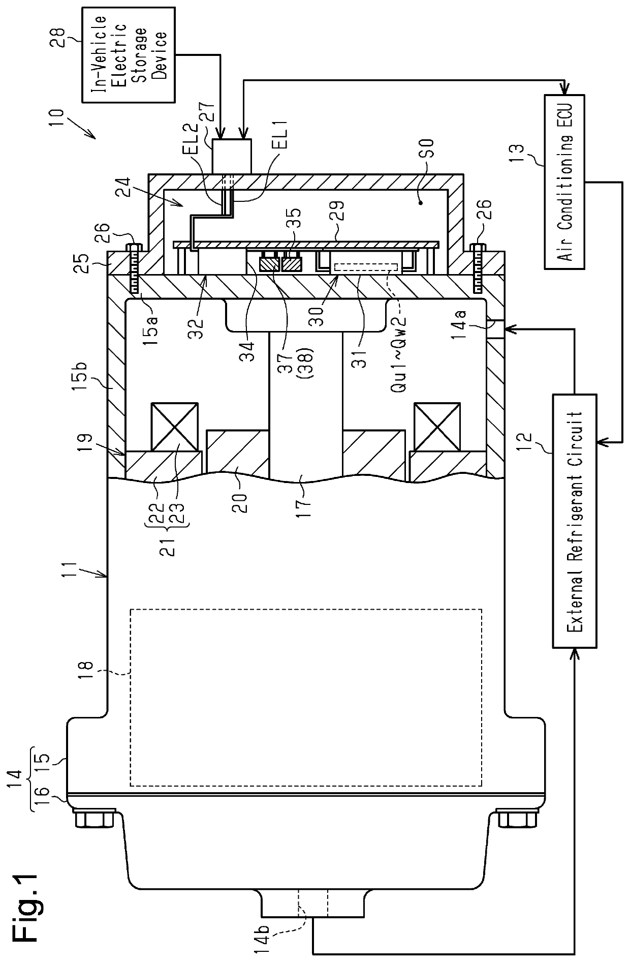
[0041]An in-vehicle motor-driven compressor 11 according to a first embodiment will now be described with reference to the drawings. The in-vehicle motor-driven compressor 11 of the present embodiment includes a compression unit 18 that compresses fluid, which is refrigerant, and is used in an in-vehicle air conditioner 10. That is, the fluid to be compressed in the in-vehicle motor-driven compressor 11 in the present embodiment is a refrigerant.

[0042]As shown in FIG. 1, the in-vehicle air conditioner 10 includes the in-vehicle motor-driven compressor 11 and an external refrigerant circuit 12. The external refrigerant circuit 12 supplies fluid, which is a refrigerant, to the in-vehicle motor-driven compressor 11. The external refrigerant circuit 12 includes, for example, a heat exchanger and an expansion valve. The in-vehicle motor-driven compressor 11 compresses the refrigerant, and the external refrigerant circuit 12 performs heat exchange and expansion of the refrigerant. Accordi...

second embodiment

[0114]A second embodiment will now be described. Differences from the first embodiment will be mainly discussed.

[0115]The second embodiment employs the structure shown in FIGS. 12A, 12B, 12C, and 12D instead of the structure shown in FIGS. 3A3B, 3C, and 3D.

[0116]In FIGS. 12A, 12B, 12C, and 12D, a common mode choke coil 90 includes an annular core 100, which includes a through-hole 100a on the inner side, a first winding 110, which is wound around the core 100, a second winding 111, which is wound around the core 100, and a metal thin film 120, which is an annular conductor. The second winding 111 is opposed to the first winding 110 while being spaced apart from the first winding 110. The metal thin film 120 covers the core 100 while extending over the first winding 110 and the second winding 111.

[0117]As shown in FIGS. 13A and 13B, the core 100 includes, as viewed in the axial direction, a first straight section 101, a second straight section 102, a first arcuate section 103, which ...


PUM


Abstract

An in-vehicle motor-driven compressor includes a common mode choke coil including an annular core having a through-hole, a first winding and a second winding wound around the core, and an annular conductor. The second winding is opposed to the first winding while being spaced apart from the first winding. The conductor surrounds the first and second windings, and the core. The conductor includes sections opposed to each other with the through-hole in between. The core is symmetrical with respect to at least one symmetry axis when the through-hole is viewed from the front. The first winding is located on one side of the at least one symmetry axis, and the second winding is located on the other side of the symmetry axis, so that the at least one symmetry axis is located between the first and second windings. The core includes an exposed section not covered with the conductor.

Description

BACKGROUND1. Field[0001]The present disclosure relates to an in-vehicle motor-driven compressor.2. Description of Related Art[0002]International Publication WO 2017 / 170817 discloses a choke coil covered with a conductor as a configuration of a common mode choke coil used in an inverter device that drives an electric motor in an in-vehicle motor-driven compressor. When a normal-mode current flows through such a choke coil, leakage magnetic flux is generated. The leakage magnetic flux in turn causes an induced current to flow through the conductor. The induced current is converted into a thermal energy in the conductor. The choke coil thus has a damping effect.[0003]In a case where a choke coil is entirely covered with a conductor, the heat is likely to be trapped inside. On the other hand, if a choke coil is designed to have a section not covered with a conductor in order to enhance the heat radiation performance, induced current would not flow readily in that section, reducing the d...

Claims


Application Information

Patent Timeline
Patent Type & Authority Applications(United States)
IPC IPC(8): F04B35/04H02M1/12H02M7/00
CPCF04B35/04B60W10/08H02M7/003H02M1/126H01F27/2895H01F27/28H01F27/24H02M1/14H02M7/219H02M1/123H01F37/00H01F27/363H01F27/324
Inventor FUKASAKU, HIROSHINAGATA, YOSHIKIKAWASHIMA, TAKASHIAMBO, SHUNSUKEKAIDA, JUNYA
Owner TOYOTA IND CORP
Why Eureka
Try Eureka