Engine starting apparatus

a technology for starting equipment and engines, which is applied in the direction of engine starters, machines/engines, transportation and packaging, etc., can solve the problems of difficult miniaturization of batteries and likely increase of motor power consumption, and achieve the effects of reducing the rated output of batteries, reducing motor power consumption, and miniaturizing batteries

Inactive Publication Date: 2013-09-12
TOYOTA JIDOSHA KK
View PDF0 Cites 23 Cited by
  • Summary
  • Abstract
  • Description
  • Claims
  • Application Information

AI Technical Summary

Benefits of technology

[0013]Thus, for example, it is possible to reduce the power consumption of the motor in the expansion stroke after the number of revolutions of the engine reaches the predetermined number of revolutions of the engine, in comparison with a case where the cranking base torque is set to the first torque value even in the expansion stroke after the number of revolutions of the engine reaches the predetermined number of revolutions of the engine. Therefore, it is possible to reduce the rated output of the battery (the maximum value of the electric power that the battery can output) for supplying the electric power to the motor, thereby miniaturizing the battery. Incidentally, as described above, the vibration controlling torque is typically controlled to reduce the torque outputted by the motor if the piston is in the compression stroke and to increase the torque outputted by the motor if the piston is in the expansion stroke. Thus, if the cranking base torque is set to the same torque value between the compression stroke and the expansion stroke, the target torque is maximal in the expansion stroke.
[0014]Here, in the expansion stroke, the rotation of the crankshaft is accelerated by the expansion of the air compressed in a cylinder in the compression stroke. Thus, in the expansion stroke, the number of revolutions of the engine tends to easily increase than in the compression stroke. Thus, in the present invention, the cranking base torque in the expansion stroke is reduced less than the cranking base torque in the compression stroke by the rotation of the crankshaft being accelerated by the expansion of the air compressed in the cylinder in the compression stroke,. This makes it possible to avoid a wasteful increase in the power consumption of the motor in the expansion stroke while increasing the number of revolutions of the engine.
[0015]As explained above, according to the engine starting apparatus of the present invention, it is possible to suppress the vibration of the power transmission system due to the resonance of the damper at the start of the engine and to suppress the power consumption of the motor.

Problems solved by technology

However, if a torque obtained by applying the vibration controlling torque to the cranking base torque is outputted from the motor, depending on a time-dependent change in the cranking base torque and the vibration controlling torque, the maximum value of the torque to be outputted from the motor likely becomes greater than that in a case where only the cranking base torque is outputted from the motor and the power consumption of the motor likely increases.
Thus, the rated output of a battery for supplying electric power to the motor (i.e. the maximum value of the electric power that the battery can output) needs to be increased, and it is hard to miniaturize the battery, which is technically problematic.

Method used


Image

  • Engine starting apparatus
  • Engine starting apparatus
  • Engine starting apparatus

Examples


first embodiment

[0030]An engine starting apparatus in a first embodiment will be explained with reference to FIG. 1 to FIG. 4.

[0031]Firstly, the entire configuration of a hybrid vehicle to which the engine starting apparatus in the embodiment is applied will be explained with reference to FIG. 1.

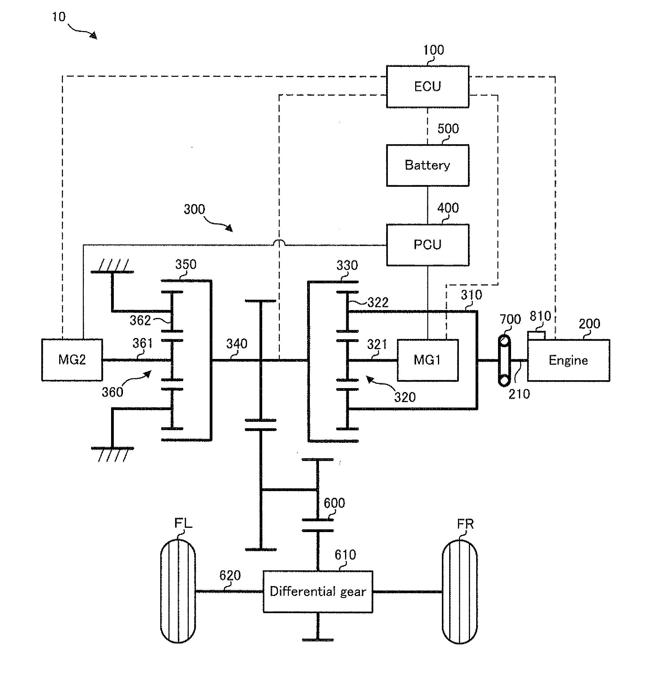
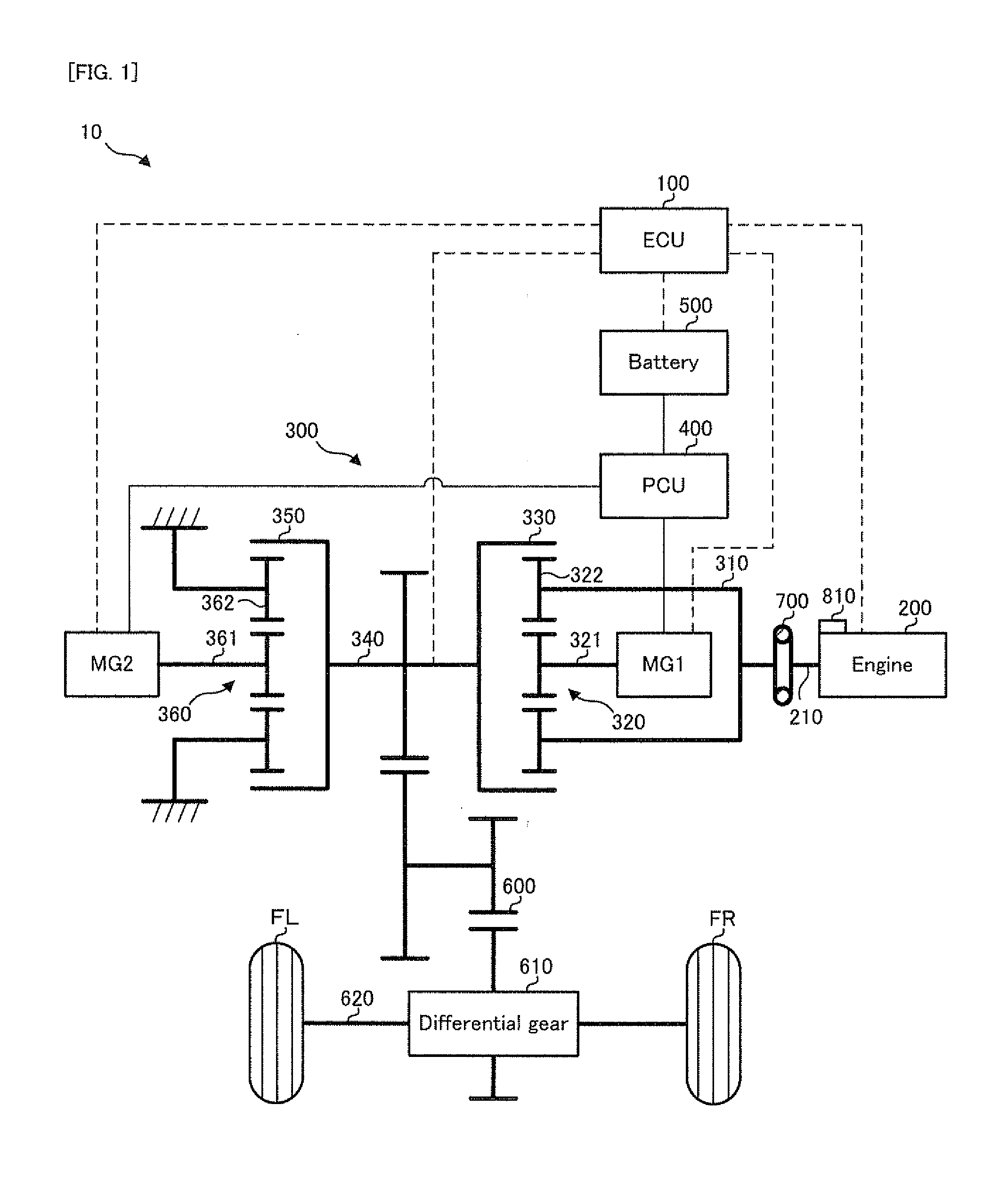
[0032]FIG. 1 is a schematic configuration diagram conceptually showing the configuration of the hybrid vehicle in the embodiment.

[0033]In FIG. 1, a hybrid vehicle 10 in the embodiment is provided with an electronic control unit (ECU) 100, an engine 200, a motor generator MG1, a motor generator MG2, a power dividing mechanism 300, a power control unit (PCU) 400, a battery 500, a transmission mechanism 600, a differential gear 610, a transmission shaft 620, a damper 700, a crank position sensor 800, and drive wheels FR and FL.

[0034]The ECU 100 is provided with a central processing unit (CPU), a read only memory (ROM), and a random access memory (RAM) or the like, and it is an electronic control unit capable o...

second embodiment

[0076]An engine starting apparatus in a second embodiment will be explained with reference to FIG. 6 and FIG. 7.

[0077]FIG. 6 is a flowchart showing a flow of controlling the cranking base torque in the second embodiment. FIG. 7 is a graph showing one example of a time-dependent change in the cranking base torque and the number of revolutions of the engine in the second embodiment. Incidentally, in FIG. 6, the same steps as those in the control of the cranking base torque in the first embodiment shown in FIG. 4 will carry the same step numbers, and the explanation thereof will be omitted as occasion demands.

[0078]In FIG. 7, the engine starting apparatus in the second embodiment is configured to be different from the engine starting apparatus in the first embodiment described above in the point of controlling the cranking base torque to start to be reduced from the first torque value BT1 at a time point Tcs1 at which the piston of the engine 200 reaches the compression stroke for the ...

third embodiment

[0084]An engine starting apparatus in a third embodiment will be explained with reference to FIG. 8 and FIG. 9.

[0085]FIG. 8 is a flowchart showing a flow of controlling the cranking base torque in the third embodiment. FIG. 9 is a graph showing one example of a time-dependent change in the cranking base torque and the number of revolutions of the engine in the third embodiment. Incidentally, in FIG. 8, the same steps as those in the control of the cranking base torque in the first embodiment shown in FIG. 4 will carry the same step numbers, and the explanation thereof will be omitted as occasion demands.

[0086]In FIG. 9, the engine starting apparatus in the third embodiment is configured to be different from the engine starting apparatus in the first embodiment described above in the point of controlling the cranking base torque to be greater than the first torque value BT1 in at least one portion of a period in which the piston of the engine 200 is in the compression stroke for the ...


PUM


Abstract

An engine starting apparatus is provided with: a target torque setting device for setting a sum of a cranking base torque for cranking an engine and a vibration controlling torque for suppressing vibration of a power transmission system due to resonance of a damper, as a target torque to be outputted by a motor in cranking the engine; and a motor controlling device for controlling the motor to output the set target torque. The target torque setting device has a base torque controlling device for setting the cranking base torque to a first torque value if the number of revolutions of the engine is less than or equal to predetermined number of revolutions of the engine and for controlling the cranking base torque.

Description

TECHNICAL FIELD[0001]The present invention relates to an engine starting apparatus for staring an engine in a vehicle such as, for example, a hybrid vehicle, which is provided with the engine and a motor.BACKGROUND ART[0002]As this type of apparatus, an apparatus for motoring or cranking an engine with a motor generator connected to a crankshaft of the engine (internal combustion engine) through a damper is known (e.g. refer to patent documents 1 and 2).[0003]For example, the patent document 1 discloses a technology for increasing the number of times to motor and start the engine in the condition that there is little fuel left to be supplied to the engine. For example, the patent document 2 discloses a technology for starting fuel injection to the engine and ignition on the basis of a torsion angle of the damper at the start of the engine.[0004]On the other hand, if the damper is included in a power transmission system (power train) for transmitting the power of the engine, torque v...

Claims


Application Information

Patent Timeline
Patent Type & Authority Applications(United States)
IPC IPC(8): F02N11/08B60L50/16
CPCF02D29/02F02D2250/28F02N11/04F02N11/08F02N2200/022F02N2300/104F02N15/00Y02T10/72
Inventor YAMAGUCHI, TAKUYAKAWAI, TAKASHI
Owner TOYOTA JIDOSHA KK
Why Eureka
Try Eureka