Wheelchair

a technology for wheelchairs and wheelchairs, applied in the direction of wheelchairs/patient conveyances, nursing beds, transportation and packaging, etc., can solve the problems of poor traction, poor traction, and spinout of configurations, and achieve the effect of improving traction and traction

Inactive Publication Date: 2005-10-27
SUNRISE MEDICAL HHC INC
View PDF25 Cites 60 Cited by
  • Summary
  • Abstract
  • Description
  • Claims
  • Application Information

AI Technical Summary

Problems solved by technology

Front wheel drive configurations provide greater curb climbing ability because the drive wheels contact the curb first but produce poor traction because the wheelchair occupant's weight is concentrated towards the rear of the wheelchair.
These configurations also tend to spin out, or lose control at high speeds.
Mid-wheel drive configurations provide the tightest turning radius but also suffer from poor traction and spin out.
Front and mid-wheel drive configurations suffer from what is commonly referred to as “power spin”.
The spin is exacerbated by one drive wheel losing traction due to the centrifugal force acting on the turning chair, resulting in an uncontrolled spin.
However, this is not possible with a conventional wheelchair configuration, as the wheelchair would no longer be able to maneuver if the casters were inhibited from turning.
Front and rear wheel drive wheelchairs suffer because the turning centers of such wheelchairs are respectively positioned towards the front or rear of the wheelchair.
Furthermore, front wheel drive wheelchairs suffer because the turning center is not centered about the wheelchair occupant.
The wheelchair control is awkward because the rear of the wheelchair sweeps a large, non-intuitive path when turning in tight confines.
All conventional wheelchairs are limited in their ability to maneuver.
Purely left or right translation, or motion along a diagonal is not possible.
Typically, casters are positioned near the wheelchair occupant foot region and limit available foot space.

Method used


Image

  • Wheelchair
  • Wheelchair
  • Wheelchair

Examples


Embodiment Construction

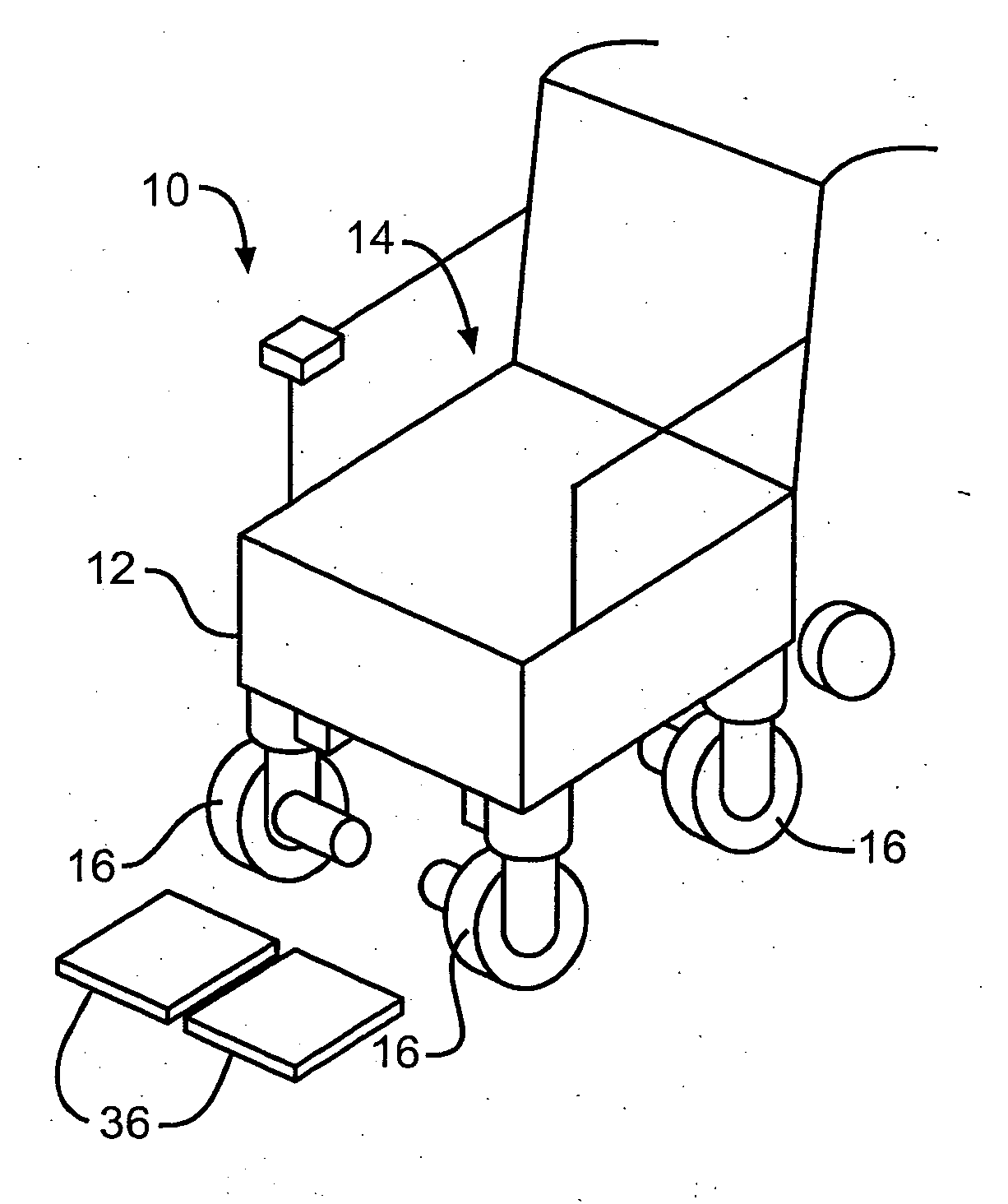
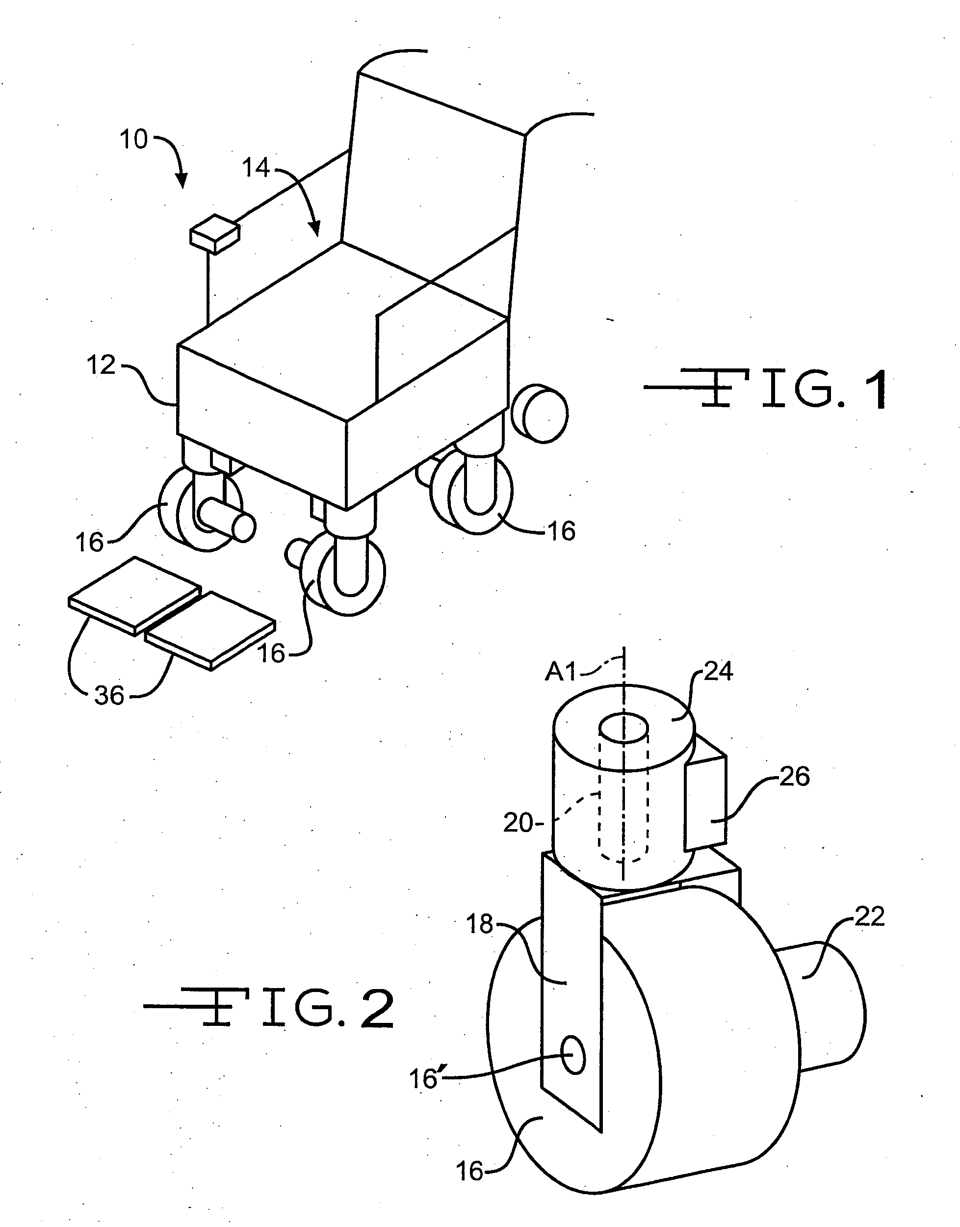
[0020] Referring now to the drawings, there is illustrated in FIG. 1 a powered wheelchair 10. The wheelchair 10 comprises a frame 12, a seat 14 for supporting a wheelchair occupant, and a plurality of wheels 16 that are adapted to support the frame 12 for movement relative to a supporting surface. Each wheel 16 resembles a caster. That is to say, each wheel 16 is supported for rotational movement about a respective axle 16′ by a fork 18, as clearly shown in FIG. 2. Each fork 18 is supported for rotational movement about a vertical axis A1, which is coincident with a spindle or stem 20, which is preferably centered above the wheel 16, to allow the wheel 16 to steer in the desired direction. At least one wheel 16, and most preferably each wheel 16, is powered by a drive motor 22, such as an in-wheel or near wheel motor, or similar prime mover for propulsion of the wheelchair 10. The motor 22 is situated near the fork 18 and allows the wheel 16 to rotate 360 degrees about the axis A1 t...


PUM


Abstract

A powered wheelchair comprises three or more wheels for supporting the wheelchair relative to a supporting surface. The three or more wheels are adapted to be steered independently of one another to steer the wheelchair in virtually any direction. At least one of the wheels is adapted to be driven for propelling the wheelchair on the supporting surface.

Description

CROSS REFERENCE TO RELATED APPLICATIONS [0001] This application claims the benefit of U.S. Provisional Patent Application No. 60 / 565,732, filed on Apr. 27, 2004.BACKGROUND OF INVENTION [0002] This invention relates in general to motor vehicles and, more particularly, to drive and steering systems for motorized vehicles. Most particularly, the invention relates to powered wheelchair drive and steering systems. [0003] A conventional wheel configuration for a powered wheelchair typically includes two drive wheels (i.e., motor powered wheels) and two or four idler wheels or casters. Steering of the wheelchair is effected by causing the drive wheels to rotate at different speeds and / or directions. A typical wheelchair caster includes a wheel, a fork, and a stem. The stem is adapted to rotate about a vertically oriented axis. Caster stem bearings or bushings allow the stem to rotate smoothly, with low friction. The fork extends from the stem and supports the wheel for rotational movement ...

Claims


Application Information

Patent Timeline
Patent Type & Authority Applications(United States)
IPC IPC(8): A61G5/04A61G7/05B60K17/30B60L15/20B62D5/06B62D7/15
CPCA61G5/046A61G2005/1051Y02T10/7258A61G2203/14B62D7/1509A61G2007/0528A61G5/1051A61G7/0528Y02T10/72
Inventor KOELIN, JAMES M.RUNKLES, RICHARD
Owner SUNRISE MEDICAL HHC INC
Why Eureka
Try Eureka