Cervical immobilizing device

a cervical and immobilizing technology, applied in the field of head and cervical immobilizing devices, can solve problems such as certain limitations of devices, and achieve the effect of preventing head twisting and reducing or eliminating the movement of patients' heads

Inactive Publication Date: 2005-10-27
AMBU AS
View PDF15 Cites 0 Cited by
  • Summary
  • Abstract
  • Description
  • Claims
  • Application Information

AI Technical Summary

Benefits of technology

[0008] Accordingly, a primary object of the invention is to provide a cervical immobilization device that is compact during storage and can be erected to a supporting position when needed.
[0009] Another object of the invention is to provide a cervical immobilization device that can be manufactured economically using inexpensive and readily available materials.
[0010] A further object of the invention is to provide a head immobilization device for attaching to a rigid backboard which can be folded to conform to a patient's head that is efficient and easy to use.
[0012] Still another object of the invention is to provide a cervical immobilization device having an actuator member that enables head engaging arms to simultaneously and symmetrically engage a patient's head when folded to an operating position to eliminate or reduce movement of the patient's head.
[0013] Another object of the invention is to provide a cervical immobilization device having an actuator device that can be operated by the user with one hand to symmetrically engage both sides of the patients head to prevent twisting of the head and to support the patient's head during transport of the patient.

Problems solved by technology

However, these devices have certain limitations and there is a continuing need in the industry for improved head immobilizing devices.

Method used


Image

  • Cervical immobilizing device
  • Cervical immobilizing device
  • Cervical immobilizing device

Examples


first embodiment

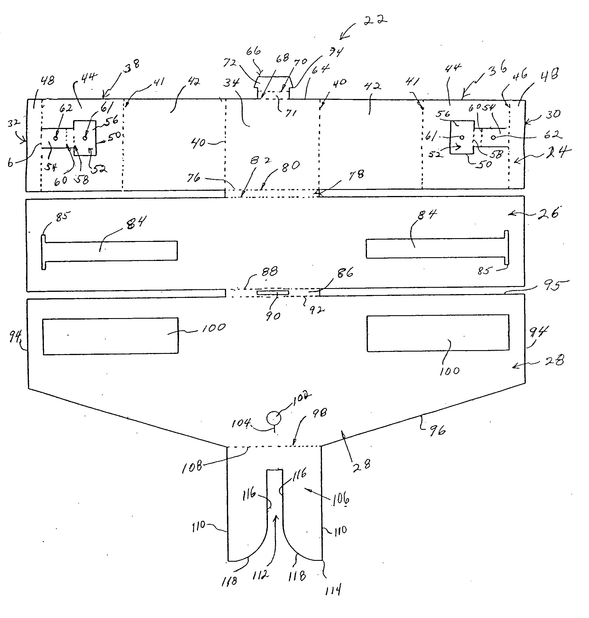
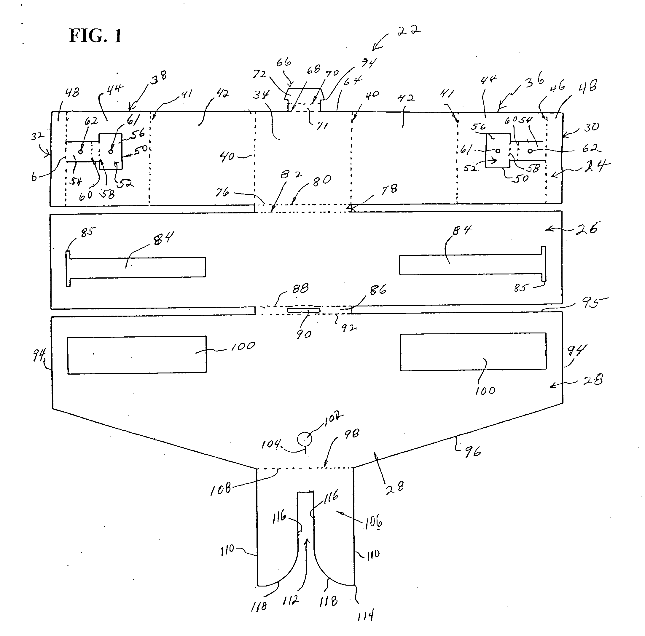
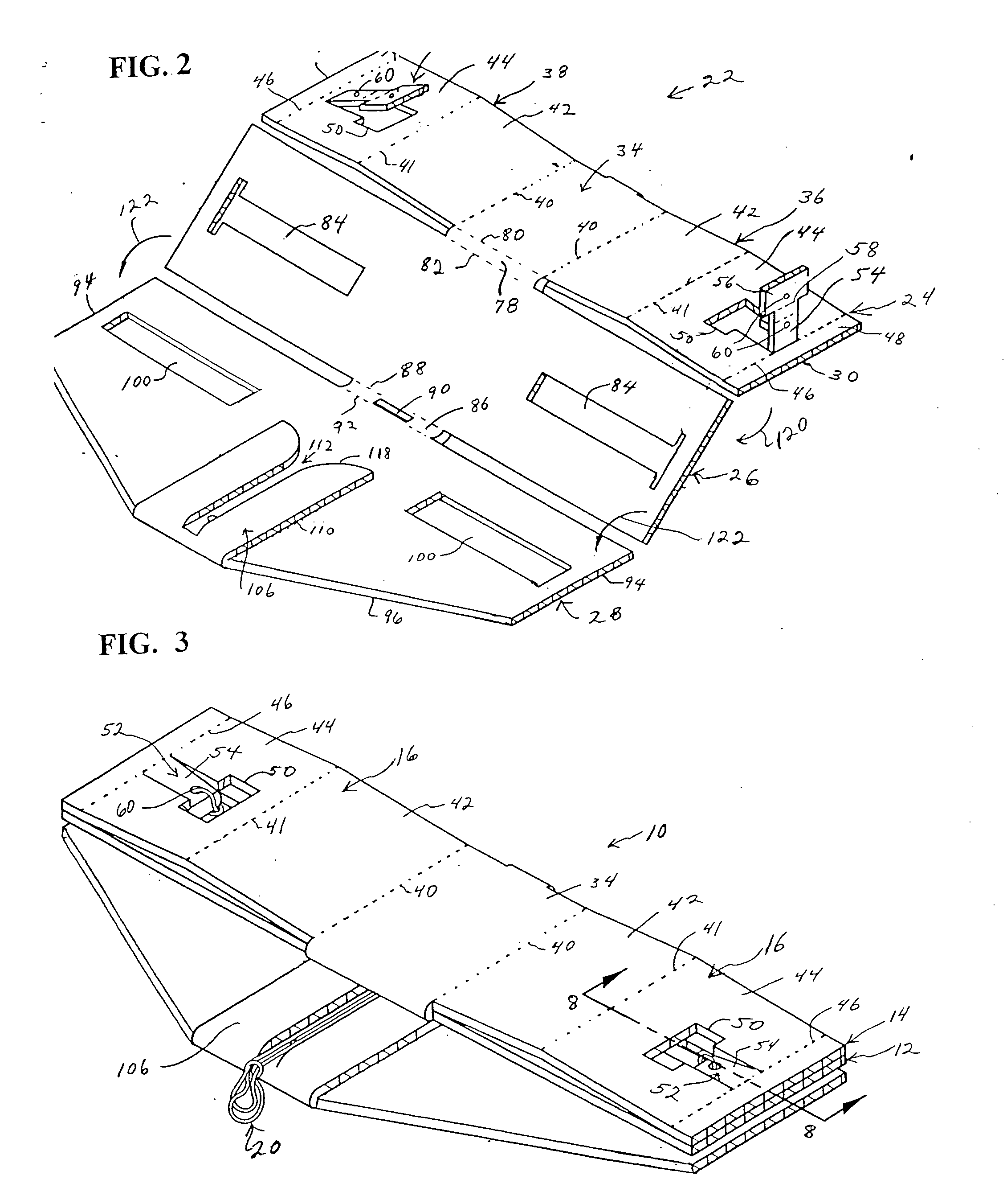
[0041] Referring to FIGS. 1-8, the assembled cervical immobilizing device 10 and blank 22 are shown. As shown in FIGS. 3-5, the device 10 includes a first base panel 12 and a top panel 14. The top panel 14 includes two opposing arms 16 that can be folded from a flat position as shown in FIG. 3 to a folded upright position as shown in FIG. 7. An actuating device 20 is attached to each of the arms 16 so that the arms 16 can be folded to an upright position substantially simultaneously and symmetrically. Folding the arms 16 symmetrically enables the arms to simultaneously engage the two sides of the patient's head to minimize movement of the head and spine while attempting to stabilize an injured patient. In further embodiments, the actuator device is able to move the arms to an upright position one at a time. For this purpose, two actuator devices can be used.

[0042] The cervical immobilizing device 10 of the invention is generally made from a suitable sheet material having sufficient ...

second embodiment

[0058] the cervical immobilizing device 133 of the invention is illustrated in FIGS. 9-11 and is similar to the immobilizing device 10 of the embodiment of FIG. 1 except for the actuating device 134. The cervical immobilizing device 133 of this embodiment is made from a blank substantially the same as the blank 22 of FIG. 1. Accordingly, identical components and parts of the immobilizing device 133 are identified by the same reference number. In this embodiment, the actuating device 134 includes a body portion 136 having a plurality of ratcheting teeth 138 on opposite sides of the body portion 136. A gripping end 140 is provided in the form of a loop. In this embodiment, a slit 142 is provided along the fold line 108 having a length substantially equal to the width of the body portion 136 and less than the outer dimension of the teeth 138. A transverse slit 144 is cut perpendicular to the slit 142 to allow the loop 140 to be inserted and positioned in the slit 142. In the embodiment...

third embodiment

[0060]FIGS. 12-15 illustrate the invention. In this embodiment, the immobilizing device 150 is similar to the device of FIG. 1 so that similar elements are identified by the same reference number. FIG. 12 shows a blank 151 for forming the immobilizing device 150 and includes panels 24, 26, 28 and 106 that are substantially the same as the previous embodiments. This embodiment differs primarily from the embodiment of FIG. 1 in that the outer panels 44 include a cut portion 50 to form tabs 152 having a substantially trapezoidal-shaped head 154. As shown, the head 154 includes angled sides 156 which converge toward the neck portion 158.

[0061] The slots 100 in panel 26 include a plurality of teeth 160 extending inwardly from each side of the slot. The teeth 160 are dimensioned to interlock with the angled sides 156 of the tabs 152. As shown, the teeth have a first face 161 angled in the direction of the outer edges and a second face 163 extending substantially perpendicular to the side ...


PUM


Abstract

A cervical immobilizing device includes a pair of arms that can be folded to an upright position to engage and support a patient's head, an actuating device for folding the arms to the supporting position, and a locking device for locking the position of the arms in the folded supporting position. The actuating device is coupled to the outer ends of the arms for folding the arms to an upright position symmetrically and uniformly. In one embodiment, the actuator device is flexible member that passes around a guide to a position which can be gripped by the user. The locking device can be a cinching, ratcheting or clamping device, or a combination thereof, on the actuator device. In one embodiment, the folding arms include a coupling device for coupling the arms to a base in a sliding arrangement to enable the arms to slide along the base to a folded position. A blank is also disclosed that can be folded to form the cervical immobilizing device.

Description

FIELD OF THE INVENTION [0001] The present invention relates generally to a head and cervical immobilization device. More particularly, the invention is directed to a cervical immobilization device that can be erected symmetrically to minimize movement of the head of an injured patient. BACKGROUND OF THE INVENTION [0002] During the transport of patients or accident victims that have suffered cervical injuries, it is essential to immobilize the head and cervical portions to prevent further injury. A variety of head and cervical immobilization devices have been used in the emergency medical industry for many years. Several of these devices are designed to fold flat during storage and can be erected when needed. [0003] One type of head immobilizing device is designed to be attached to a rigid backboard. Other devices include a rigid structural portion that do not require the use of a rigid backboard. Examples of this type of device are disclosed generally in U.S. Pat. No. 4,034,748 to W...

Claims


Application Information

Patent Timeline
Patent Type & Authority Applications(United States)
IPC IPC(8): A61F5/00A61F5/055
CPCY10S128/23A61F5/055
Inventor RUDY, RONALD M. JR.LEE, FREDDY T.MURPHY, THOMAS
Owner AMBU AS
Why Eureka
Try Eureka