Spinal fixation plates and plate extensions

Active Publication Date: 2005-10-27
DEPUY SPINE SARL
View PDF42 Cites 88 Cited by
  • Summary
  • Abstract
  • Description
  • Claims
  • Application Information

AI Technical Summary

Benefits of technology

[0007] Each branch portion can include at least one thru-bore formed therein, and more preferably each of the first and second branch portions includes a single thru-bore formed therein adjacent to a terminal end thereof. The thru-bore(s) in each of the first and second branch po

Problems solved by technology

However, because the area between the cervical spine and the occiput is greatly reduced, the use of bone graft material with the Y-shaped plate is limited.
While these plate constructs have provided a stable technique for occipito-cervical fixation, fixation to the occiput continues to be a challenge.
In particular, extreme variability in the thickness of the skull itself can limit the effectiveness of current plates, which must be positioned at

Method used


Image

  • Spinal fixation plates and plate extensions
  • Spinal fixation plates and plate extensions
  • Spinal fixation plates and plate extensions

Examples


Embodiment Construction

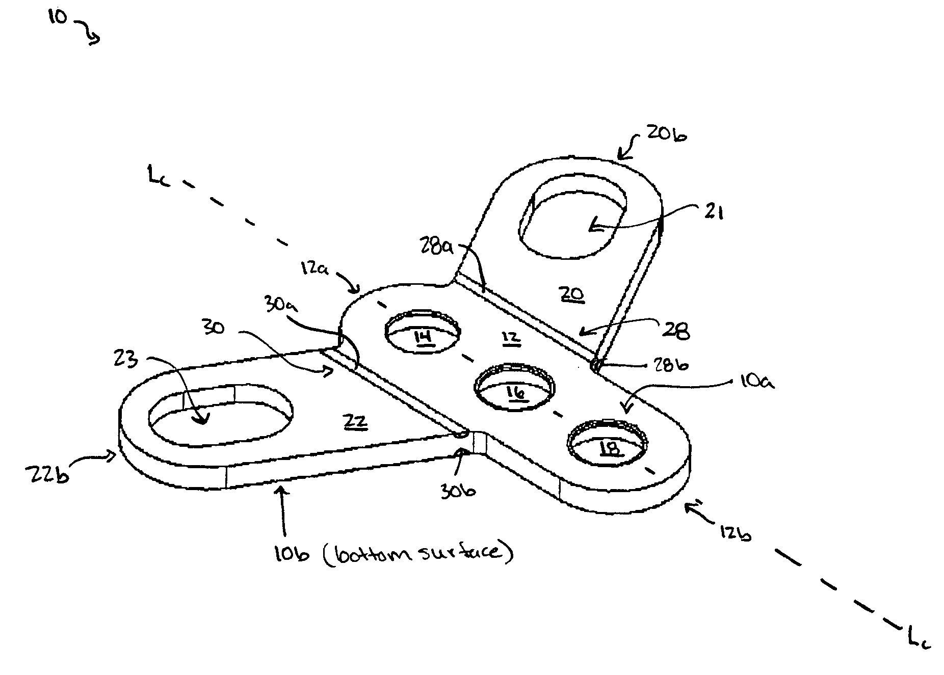
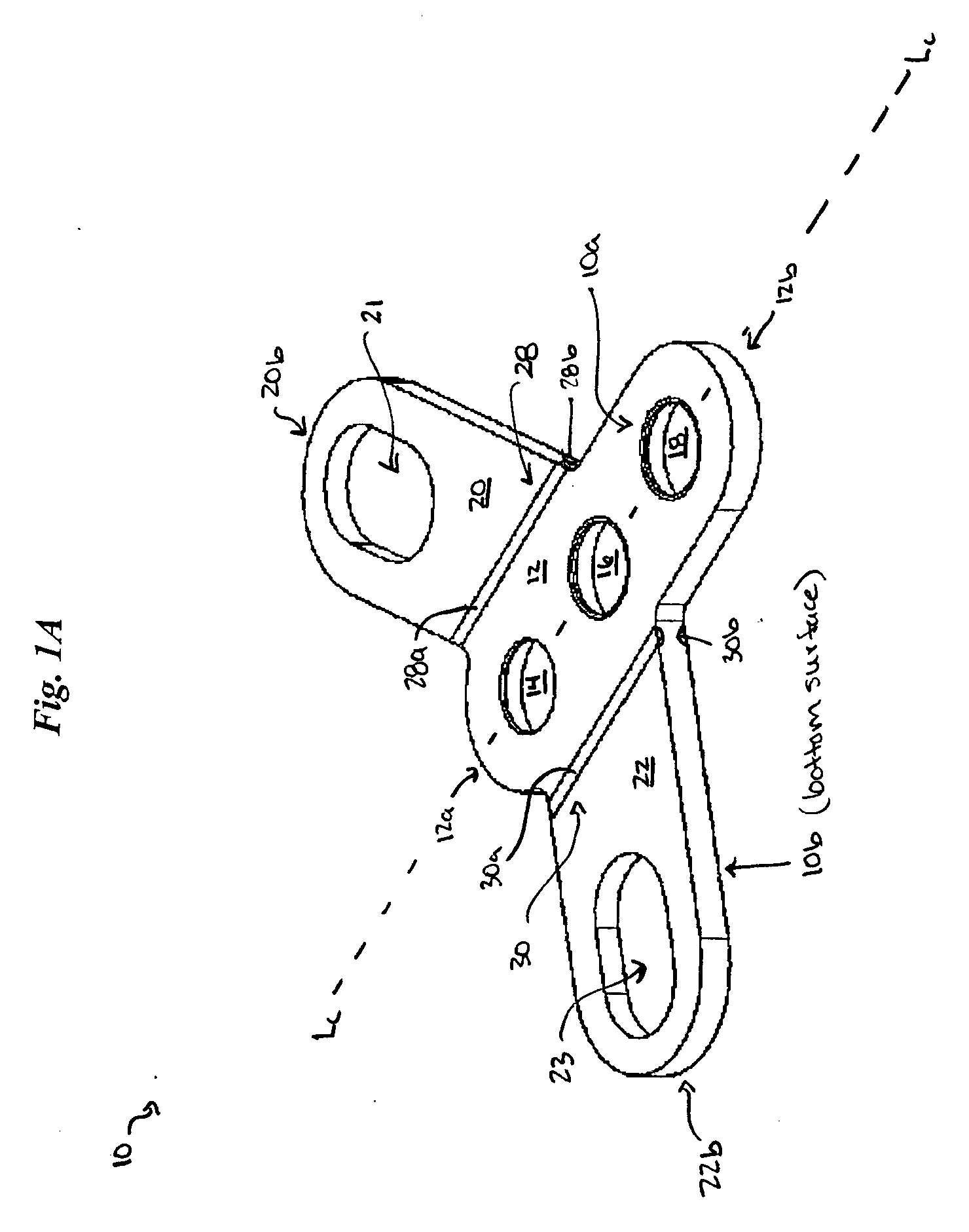
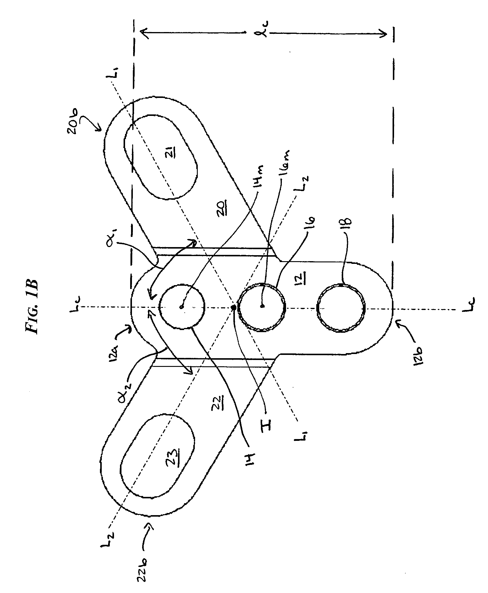
[0024] The present invention provides a spinal fixation plate that is adapted to be implanted in a variety of positions in the occiput. In general, the plate has a substantially planar configuration and it includes a mid-line or central portion having several thru-bores formed therein, and first and second opposed branch portions that extend from the central portion and that also include at least one thru-bore formed therein. The configuration of the branch portions relative to the central portion, as well as the position of the mid-line thru-bores formed in the central portion in relation to the thru-bore(s) formed in each branch portion, allow the spinal fixation plate to be implanted in a variety of positions in the occiput, thus allowing the optimal implant site to be selected. The configuration also allows a variety of other spinal fixation devices, such as spinal rods, cables, plates, etc. to be attached to the plate in an optimal position.

[0025]FIGS. 1A-1B illustrate one emb...


PUM


Abstract

A spinal fixation plate that is adapted to be implanted in a variety of positions in the occiput is provided. In general, the plate has a substantially planar configuration and it includes a mid-line or central portion having several thru-bores formed therein, and first and second opposed branch portions that extend from the central portion and that also include at least one thru-bore formed therein. The configuration of the branch portions relative to the central portion, as well as the position of the mid-line thru-bores formed in the central portion in relation to the thru-bore(s) formed in each branch portion, allow the spinal fixation plate to be implanted in a variety of positions in the occiput, thus allowing the optimal implant site to be selected.

Description

FIELD OF THE INVENTION [0001] The present invention relates to spinal fixation devices, and in particular to a spinal fixation plate that can be used in multiple orientations in a patient's spinal system. BACKGROUND OF THE INVENTION [0002] Treatment of some spinal injuries or disorders may involve the use of a spinal fixation element, such as a relatively rigid fixation rod, that is coupled to adjacent vertebrae by attaching the element to various anchoring devices, such as plates, hooks, bolts, wires, or screws. Often two rods are disposed on opposite sides of the spinous process in a substantially parallel relationship. The fixation rods can have a predetermined contour that has been designed according to the properties of the target implantation site, and once installed, the rods hold the vertebrae in a desired spatial relationship, until healing or spinal fusion has taken place, or for some longer period of time. When such surgery is performed in the cervical spine, the proximal...

Claims


Application Information

Patent Timeline
IPC IPC(8): A61B17/60A61B17/70
CPCA61B17/7055Y10S606/902A61B17/7059
Inventor BOOMER, MARK C.KALFAS, IAINMURPHY, RAYMOND F.
Owner DEPUY SPINE SARL
Why Eureka
Try Eureka