Inner sole assembly for slipper or sandal

a technology for inner soles and slippers, which is applied in the field of inner sole assembly of slippers or sandals, can solve the problems of reducing the flexibility effect and the use lifetime of the insole, reducing the comfort of wearing slippers, so as to achieve the effect of reducing the impact, reducing the impact, and reducing the impa

Inactive Publication Date: 2005-11-03
TAIWAN PAIHO LTD
View PDF7 Cites 64 Cited by
  • Summary
  • Abstract
  • Description
  • Claims
  • Application Information

AI Technical Summary

Benefits of technology

[0004] It is, therefore, the primary purpose of the present invention to provide an inner sole assembly for slippers or sandals, including a slipper or sandal made up of a sole, a retaining strap, a coupling pad, and an insole wherein the insole has a plurality of resilient supporting rings with air vents densely and neatly arranged in upright circular shapes at the upper surface thereon, and a plurality of dividing passages defined at the adjacent sides of the closely arranged resilient supporting rings thereof; whereby, in case tiny grains of sands/stones get caught inside the insole thereof, the sands/stones can be precisely flushed or knocked out there-from via the air vents of the resilient supporting rings in an easy and fast manner, preventing the sands/stones from accumulated at the resilient supporting rings therein, achieving better sand-draining effect to keep the insole thereof neat and clean in practical use.
[0005] It is, therefore, the second purpose of the present invention to provide an inner sole assembly for slippers or sandals wherein the resilient supporting rings of the insole are closely and neatly stood upright in circular shapes, efficiently sustaining the weight of the so

Problems solved by technology

There are some drawbacks to such conventional slipper 10.
After long time of frequent use thereof, sands/stones A can accumulate more and more inside the insole 12 thereof and make the slipper 10 uncomfortable and untidy to

Method used


Image

  • Inner sole assembly for slipper or sandal
  • Inner sole assembly for slipper or sandal
  • Inner sole assembly for slipper or sandal

Examples


Embodiment Construction

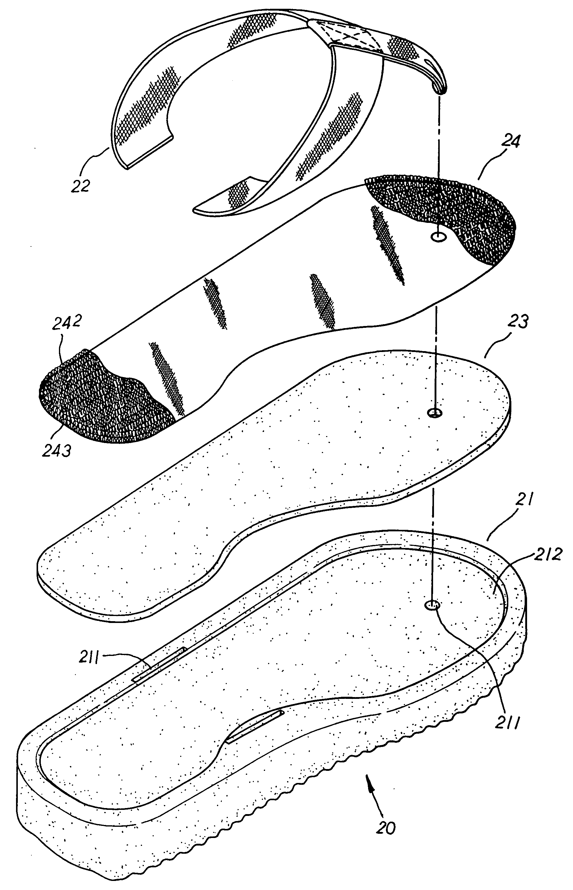
[0013] Please refer to FIG. 3. The present invention is related to an inner sole assembly for slippers or sandals, including a slipper or sandal 20 made up of a sole 21, a retaining strap 22, a coupling pad 23, and an insole 24. The sole 21 has a plurality of assembly holes 211 properly preset at the top surface thereon for the retaining strap 22 of a slipper or a sandal as shown in FIG. 6 to be fixedly engaged therewith, and a holding recess 212 of proper depth indented at the top surface thereon. The coupling pad 23, better made of EVA or PVC foaming material, is molded in conformance to the shape of the holding recess 212 thereof and with a proper thickness. The insole 24, having bamboo charcoal contained therein, is integrally woven and shaped like the holding recess 212 thereof. A multiple of resilient supporting rings 242 with air vents 241 defined therein are densely and neatly arranged and stood upright in circular shapes at the upper surface of the insole 24 thereon as show...


PUM


Abstract

An inner sole assembly for slippers or sandals includes a slipper or sandal made up of a sole, a retaining strap, a coupling pad, and an insole wherein the sole has a plurality of assembly holes properly preset at the top surface thereon for the retaining strap led through the insole and the coupling pad thereof respectively to be fixedly engaged therewith, and the coupling pad, better made of EVA or PVC foaming material, is sandwiched between the insole and the top surface of the sole to integrally combine the insole and the sole into one piece. The insole has a plurality of resilient supporting rings with air vents densely and neatly arranged in upright circular shapes at the upper surface thereon, an engaging underside formed at the bottom surface thereof to be fixedly attached to the coupling pad thereby, and a plurality of dividing passages defined at the adjacent sides of the closely juxtaposed resilient supporting rings thereof. Thus, in case tiny grains of sands/stones get caught inside the insole thereof, the sands/stones can be precisely flushed or knocked out there-from via the air vents of the resilient supporting rings in an easy and fast manner, achieving superior effect of massage as well as sand-draining and air-venting capabilities. Besides, the insole can also have bamboo charcoal contained therein to provide deodorization and anti-bacteria effects thereof.

Description

BACKGROUND OF THE INVENTION [0001] The present invention is related to an inner sole assembly for slippers or sandals, including a slipper or sandal made up of a sole, a retaining strap, a coupling pad, and an insole wherein the sole has a plurality of assembly holes distributed thereon for the retaining strap to be fixedly engaged therewith, and the coupling pad is sandwiched between the insole and the top surface of the sole to integrally combine the insole and the sole into one piece. The insole has a plurality of resilient supporting rings with air vents densely and neatly arranged in upright circular shapes at the upper surface thereon, and a plurality of dividing passages defined at the adjacent sides of the closely arranged resilient supporting rings thereof; whereby, in case tiny grains of sands / stones get caught inside the insole thereof, the sands / stones can be precisely flushed or knocked out there-from via the air vents of the resilient supporting rings in an easy and fa...

Claims


Application Information

Patent Timeline
IPC IPC(8): A43B3/10A43B3/12A43B9/00A43B13/38
CPCA43B1/0045A43B3/108A43B9/00A43B7/146A43B3/128
Inventor CHENG, SEN-MEI
Owner TAIWAN PAIHO LTD
Why Eureka
Try Eureka