Vibration-proof construction method

a construction method and vibration-proof technology, applied in the direction of shock-proofing, foundation engineering, roads, etc., can solve the problems of increasing costs, losing vibration-blocking effects, and frequent vibration disturbances along the side of roads, so as to reduce construction costs, improve vibration-proof effects, and improve the effect of vibration-proof effects

Inactive Publication Date: 2006-05-23
HIROKAZU TAKEMIYA +2
View PDF37 Cites 9 Cited by
  • Summary
  • Abstract
  • Description
  • Claims
  • Application Information

AI Technical Summary

Benefits of technology

[0010]Accordingly, it is an object of the present invention to provide a practical and excellent vibration-proof construction method wherein even better vibration-proof effects can be obtained, and also wherein contribution to reduction in construction costs can be realized.
[0011]The present inventors have intensively studied a method to improve vibration-proof effects more than ever based upon the theory regarding wave propagation within the ground described in the foregoing Japanese Patent No. 2850187, and as a result of intensive studies, have found that better vibration-proof effects than those obtained with conventional methods can be obtained by laying underground a hard member which is stiffer than the surrounding ground, and a rubber elastic member, under predetermined conditions, thereby completing the present invention.
[0012]That is to say, the vibration-proof construction method according to the present invention is a method for preventing or reducing vibration around a structure which generates vibration or receives vibration, wherein a hard member having higher stiffness than the surrounding ground and a rubber elastic member are adjacently laid underground directly underneath or around said structure, thereby forming a hard layer and a elastic layer.
[0013]With the vibration-proof construction method according to the present invention, making best use of the properties of a rubber member with a hard layer construction technique based upon the theory regarding wave propagation within the ground established by the present inventors, and perspective regarding kinetic properties of a rubber elastic member, realizes extensive improvement of damping effects for vibrational propagation in the ground. Thus, it is possible to reduce not only propagation of traffic vibrations passing through but also traffic noise extensively. Moreover, scrap tires which are actually scrap material can be used, thereby contributing to extensive reduction in construction costs. According to the present invention, a vibration-proof technique with extremely high practical value can be provided.

Problems solved by technology

In recent years, vibrational disturbances along side of roads, railroad structures, and the like have frequently occurred due to traffic vibration or mechanical vibration.
These construction methods are methods to obtain vibration-proofing effects by directly blockading vibrations which propagate in the ground by the hollow trench or by the underground wall, but the former method has difficulties not only in increased costs in order to perform additional construction for building soil-retaining structures or supporting members, because it is realistically impossible to retain the hollow trench as it is, but also in losing vibration-blocking effects due to the additional construction.
On the other hand, the latter method does nothing but replace the hollow trench with the underground wall having a constant quality of material so as to eliminate the need to perform the additional construction in the former method, so that the latter method cannot obtain sufficient vibration-proof effects as compared with the former method.
Moreover, with the above-described WIB method, a problem has remained in that anti-vibration effects are low as to vibrations with a low-frequency band of below 5 Hz, and also as to earthquakes, artificial vibration sources such as traffic vibration, and so forth, in ground influenced by low-frequency bands.

Method used


Image

  • Vibration-proof construction method
  • Vibration-proof construction method
  • Vibration-proof construction method

Examples


example 1

CONSTRUCTION EXAMPLE 1

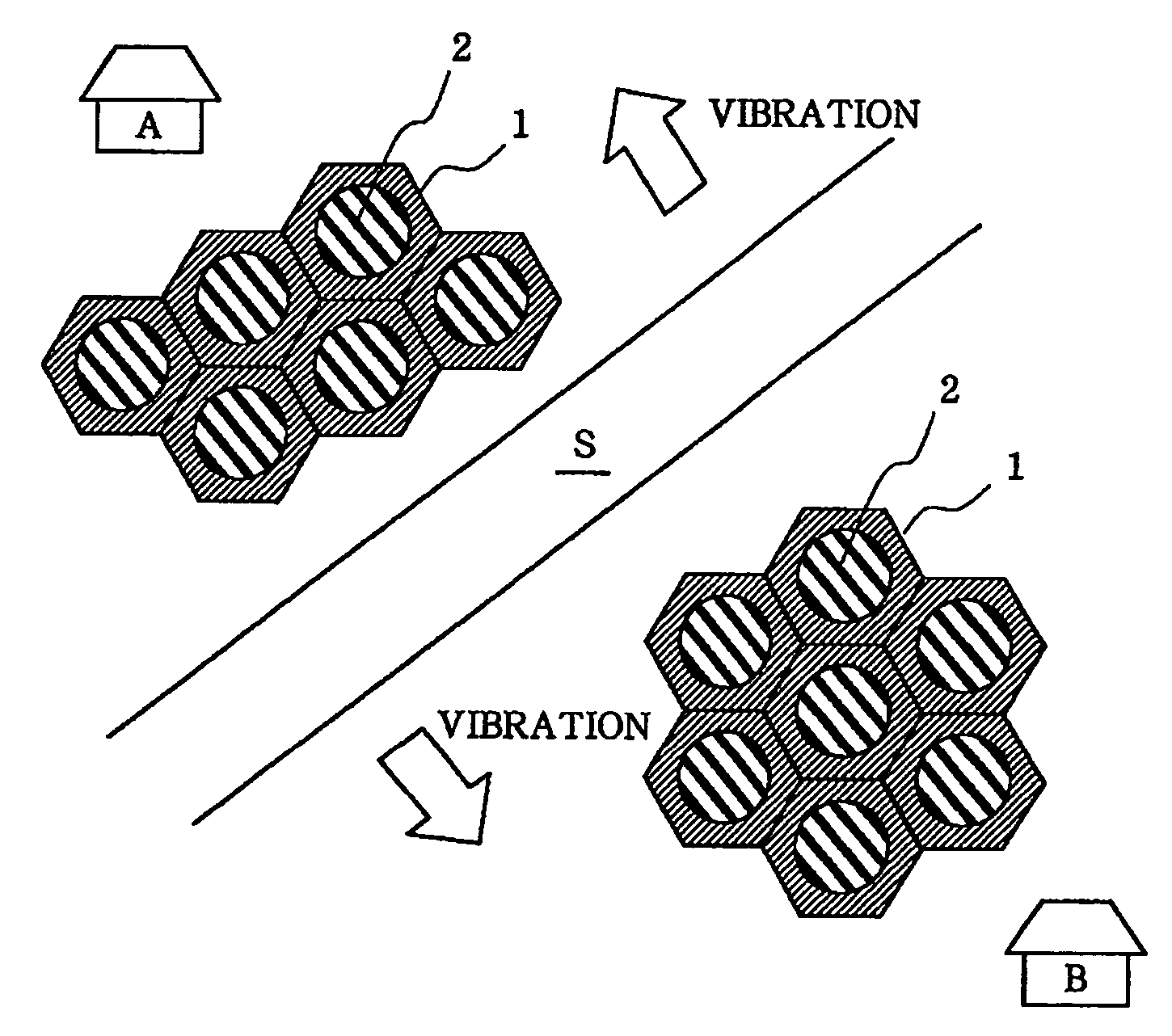
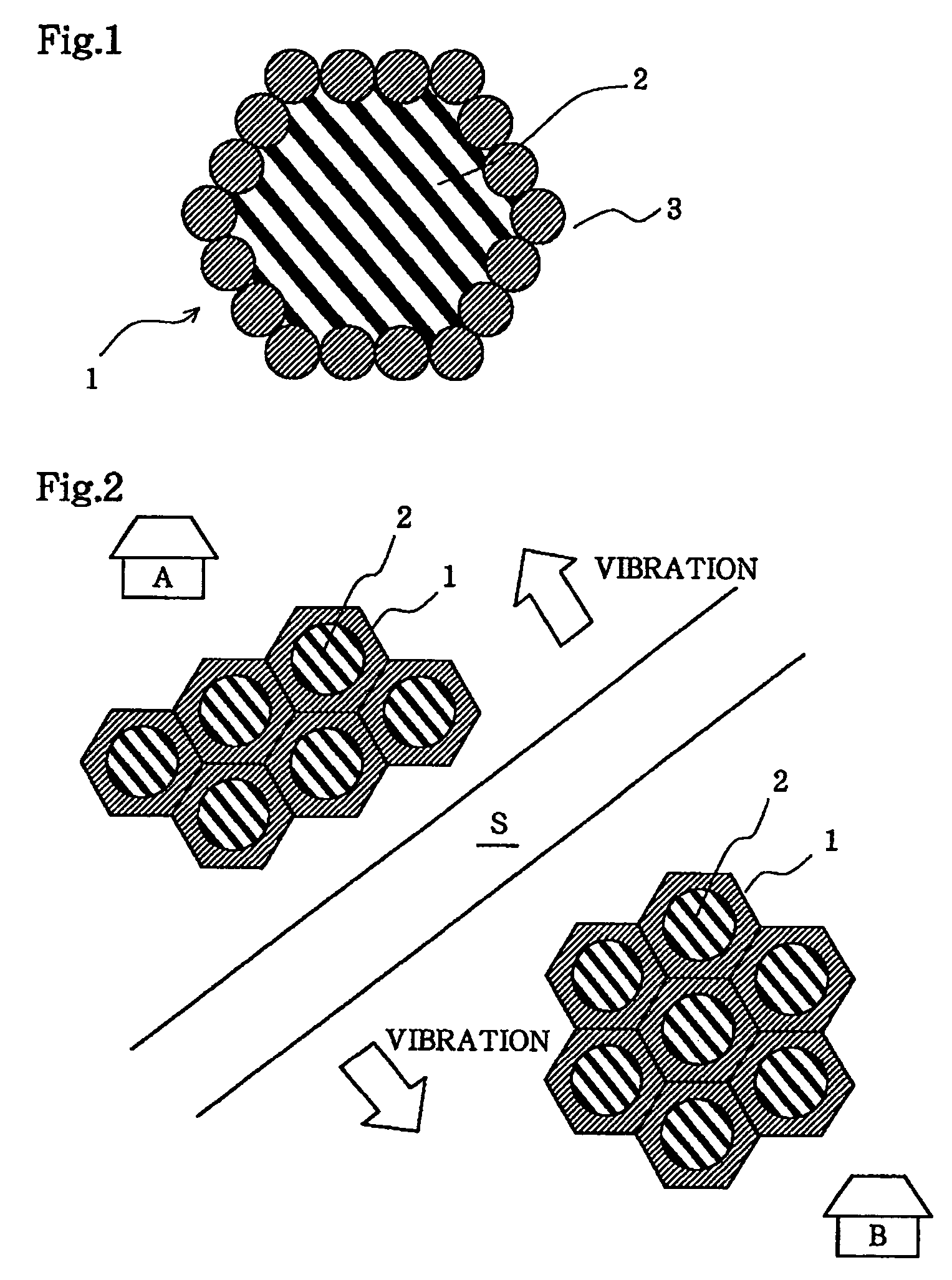
[0039]With the present preferred construction example shown in FIG. 1, schematically illustrating a cross-sectional view in the horizontal direction, a hard layer 1 is formed by driving multiple cylindrical columns 3 such that a horizontal cross-sectional shape becomes a honeycomb shape, following which an elastic layer 2 is formed by placing the for going rubber elastic member in the hard layer 1. Here, the hard layer 1 denotes the entire region formed with the multiple cylindrical columns 3. This honeycomb shape is used as a basic unit, which is appropriately placed in the ground directly underneath or around the structure which generates vibration or receives vibration. The number of cylindrical columns in one unit is preferably 5 to 50, more preferably 8 to 30, from a viewpoint of vibration-proof effects and ease of construction and the like.

[0040]As shown in FIG. 2 schematically illustrating a cross-sectional view in the horizontal direction, when there ar...

example 2

CONSTRUCTION EXAMPLE 2

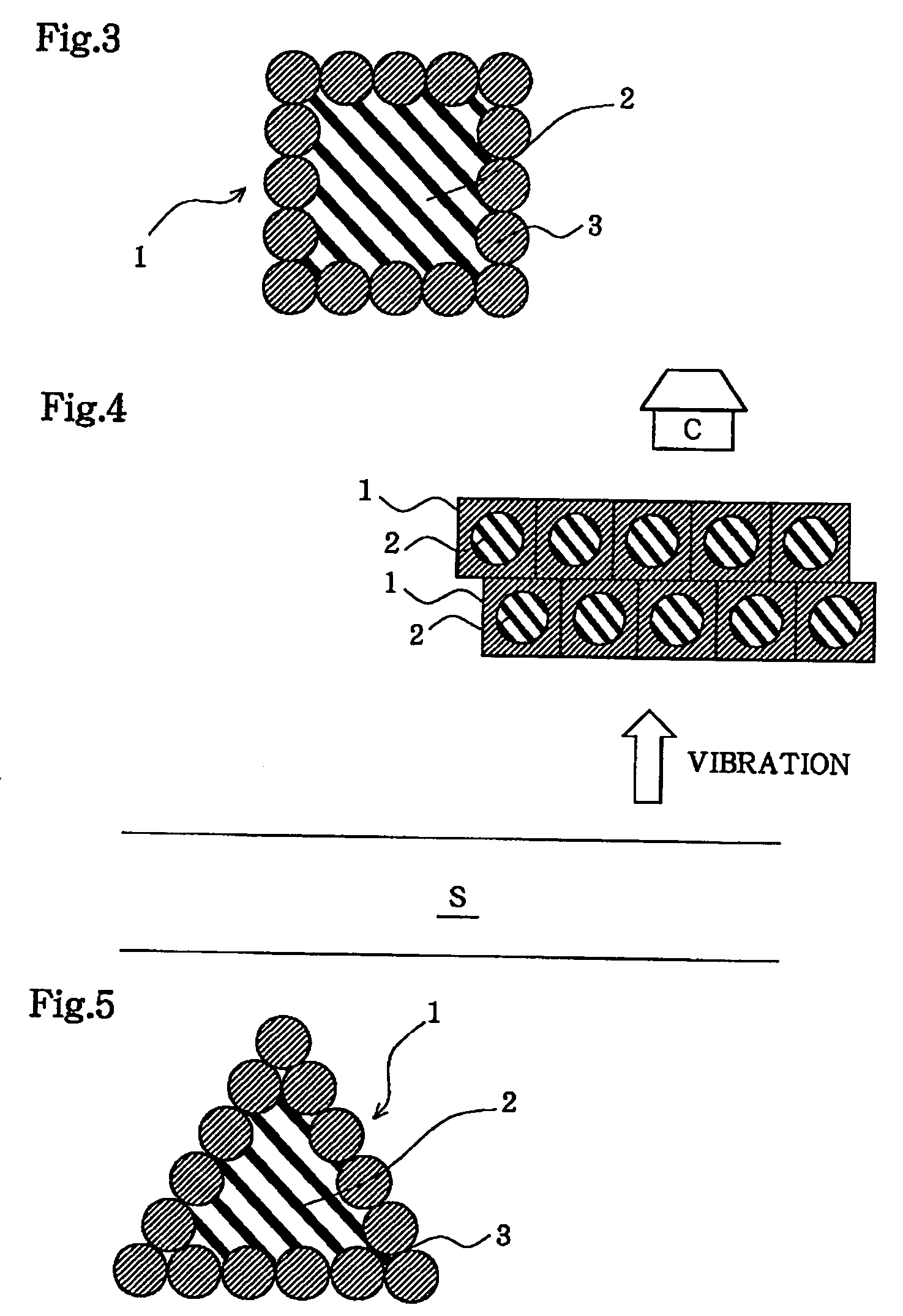
[0042]With the present preferred construction example, shown in FIG. 3 schematically illustrating a cross-sectional view in the horizontal direction, a hard layer 1 is formed by driving multiple cylindrical columns 3 such that a horizontal cross-sectional shape becomes a square shape, following which an elastic layer 2 is formed by placing the foregoing rubber elastic member in the hard layer 1. This square shape is used as a basic unit, which is appropriately placed in the ground directly underneath or around the structure which generates vibration or receives vibration. The number of cylindrical columns in one unit is preferably 5 through 50, more preferably 8 through 30, from a viewpoint of vibration-proof effects and ease of construction, as with the case of the honeycomb-shaped basic units in the foregoing Construction Example 1.

[0043]In FIG. 4, when there is a private residence C near a vibrating source S such as a road, a railroad, or the like, vibration...

example 3

CONSTRUCTION EXAMPLE 3

[0044]With the present preferred construction example shown in FIG. 5 schematically illustrating a cross-sectional view in the horizontal direction, a hard layer 1 is formed by driving multiple cylindrical columns 3 such that a horizontal cross-sectional shape becomes a triangular shape, following which an elastic layer 2 is formed by placing the foregoing rubber elastic member in the hard layer 1. This triangular shape is used as a basic unit, which is appropriately placed in the ground around the structure which generates vibration or receives vibration. The preferred number of cylindrical columns in one unit is the same as with the case of the foregoing construction examples.

[0045]In FIG. 6, when there is a private residence D near a vibrating source S such as a road, a railroad, and the like, vibration-proof construction which uses the aforementioned triangular shape for a basic unit is performed between the vibrating source S and the private residence D. W...


PUM


Abstract

A vibration-proof construction method for preventing and reducing vibration around a structure which generates vibration or receives vibration includes construction work wherein a hard member having higher stiffness than the surrounding ground and a rubber elastic member are adjacently laid underground, around or directly underneath the building structure, thereby forming a hard layer and an elastic layer. The hard member is preferably concrete, hardening-treated soil, or iron material, and the rubber elastic member is preferably scrap tires or pulverized scrap tire material. Thus, a practical and excellent vibration-proof construction method is provided, whereby even better vibration-proof effects can be obtained, and which contributes to reduction in construction costs.

Description

BACKGROUND OF THE INVENTION[0001]1. Field of the Invention[0002]The present invention relates to a vibration-proof construction method, more particularly to a vibration-proof construction method for preventing or reducing the vibrations from vibration generating sources such as a road, railroad structure, or the like, to surrounding structures and the ground surface, by suppressing vibration propagation directly underneath the vibration generating sources or in the nearby ground.[0003]2. Description of the Related Art[0004]In recent years, vibrational disturbances along side of roads, railroad structures, and the like have frequently occurred due to traffic vibration or mechanical vibration. In particular, the negative effects due to such vibrations affecting surrounding houses and residents are serious with heavy traffic or close by railway tracks, and accordingly effective and efficient countermeasures for suppressing such vibrations have been strongly demanded.[0005]As convention...

Claims


Application Information

Patent Timeline
Patent Type & Authority Patents(United States)
IPC IPC(8): E02D31/08E02D27/32E01B19/00E01C3/06
CPCE02D31/08E01C3/06E01B19/003
Inventor TAKEMIYA, HIROKAZU
Owner HIROKAZU TAKEMIYA
Why Eureka
Try Eureka