Method and apparatus for cartridge identification imprinting in difficult contexts by recess protected indicia

a cartridge identification and recess protection technology, applied in the field of identification of firearms cartridges, can solve the problems of obscuring the ballistic finger print or scratching evidence on the bullet or cartridge case, being pseudo-repeatable and largely random in nature, and being unable to identify the cartridg

Inactive Publication Date: 2005-11-03
LIZOTTE TODD E +1
View PDF41 Cites 98 Cited by
  • Summary
  • Abstract
  • Description
  • Claims
  • Application Information

AI Technical Summary

Benefits of technology

[0023] Also according to the present invention, the maximum width of the marking indicia is less than 200 microns and a maximum width of a marking land is less than 35 microns. Also, the angle of each interior wall extending between a point on a marking land and an adjacent point of a marking floor is in the range of 6 to 22.5 degrees, and the ratio between the area of the marking lands of a marking indicia and the total area of the marking indicia is in the range of 6:1 to greater than 9:1.

Problems solved by technology

Ballistic finger prints and scratch and ding markings, however, while traditionally the most useful and most used for identifying a given, specific firearm, are, however, pseudo-repeatable and largely random and non-specific in nature.
That is, a cartridge case may be damaged in any of a number of ways before it is recovered for examination, and a bullet is often severely fragmented or deformed when it strikes an object, thereby obscuring the ballistic finger print or scratch and ding evidence on the bullet or cartridge case.
For example, the surfaces of a firearm that impose markings on a bullet or cartridge are subject to wear, corrosion, abrasion and intentional alterations, such as grinding , etching or filing of surfaces and the replacement of original parts with different parts.
In addition, investigators often have limited evidence to work with in order to determine the facts related to the situation at hand, such as when the suspect firearm is unavailable, missing, unrecoverable, damaged or intentionally altered or in instances in which numerous weapons were discharged.
Therefore, while scratches, marks and / or other indicia on a spent bullet or cartridge case can assist an investigator with connecting the spent cartridge or bulletwith a given firearm, the identification usually requires possession of the firearm itself, for comparison purposes, is often difficult even when the firearm is available.
Currently, such forensic investigations are expensive and time consuming and require personal training and sophisticated equipment that not every law enforcement department has or can afford.
A number of problems in identifying cartridge cases, bullets and firearms still remain unresolved, however, even given means and methods for marking cartridge cases with identifying indicia and means for reading such indicia, such as evasion of the marking system and obtaining the maximum useful information from the marking system.
Evasion of the system is, for example, a particular problem if the marking indicia is located in or on an accessible or removable and replaceable part of a firearm.

Method used


Image

  • Method and apparatus for cartridge identification imprinting in difficult contexts by recess protected indicia
  • Method and apparatus for cartridge identification imprinting in difficult contexts by recess protected indicia
  • Method and apparatus for cartridge identification imprinting in difficult contexts by recess protected indicia

Examples


Embodiment Construction

[0039] A. Introduction

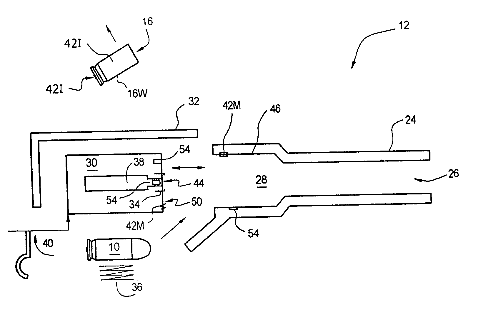
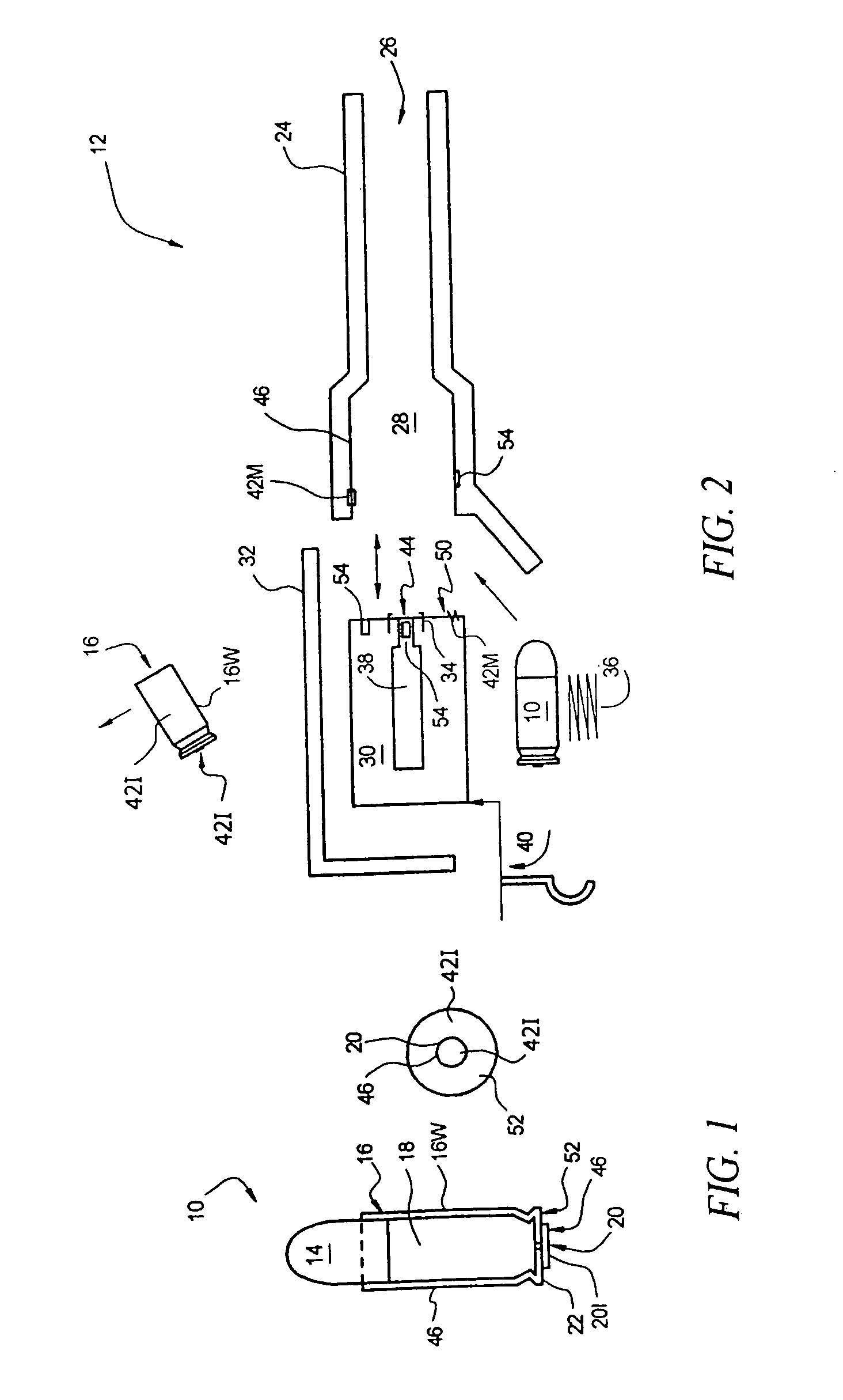
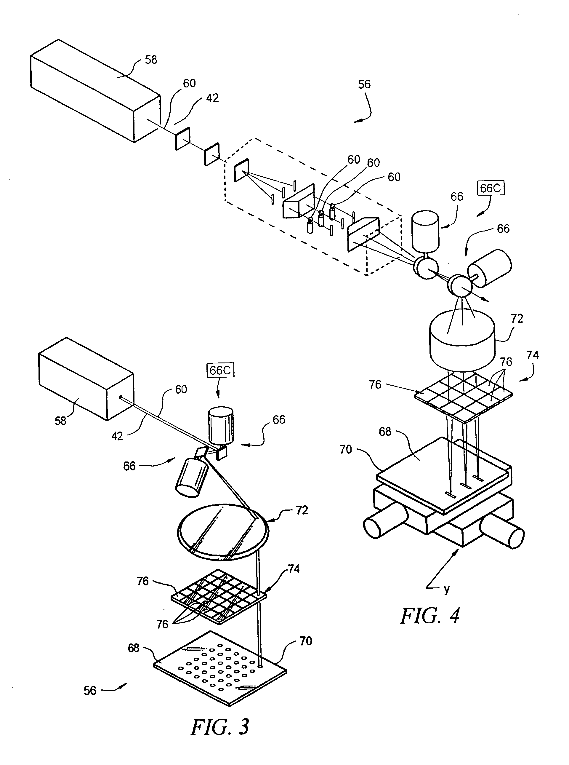
[0040] The following will first discuss the elements and operation of a typical firearm, cartridge and bullet, by way of a general introduction to parts and operations of a firearm in imposing identifying indicia on bullets or cartridge cases and to establish common definitions and points of reference. The following will then provide an introduction to the methods and apparatus for embossing or imprinting identifying indicia by a firearm on a cartridge case or bullet, following by a discussion and description of a laser system for generating or providing, on a part of a firearm, the “micro-engraving” or “micro-stamping” tool or image necessary to emboss or stamp an identifying indicia or a cartridge case or bullet.

[0041] Given foundation descriptions of the technology involved in and related to the present invention, the following will then describe the present invention and presently preferred embodiments of the invention, including presently preferred forms...


PUM


Abstract

Imprinting an identification indicia on a cartridge in a difficult context, such as on a coated cartridge or on a high power cartridge. A marking indicia is formed on a base surface located in the interior surface of a cartridge chamber containing the cartridge and includes marking lands raised with respect to the base surface and a maximum marking indicia elevation above the base surface that is coplanar with the interior surface. The marking indicia is thereby recessed with respect to the interior surface and the identification indicia is thereby recessed with respect to the imprint surface.

Description

[0001] This application is continuation in part of and claims benefit of U.S. patent application Ser. No. 10 / 622,236 filed Jul. 18, 2003, which is a continuation in part of and claims benefit of U.S. patent application Ser. No. 10 / 427,513 filed May 1, 2003, which in turn claims benefit of U.S. patent application Ser. No. 10 / 372,459 filed Feb. 21, 2003, which in turn claims benefit of U.S. patent application Ser. No. 10 / 232,766 filed Aug. 29, 2002, which in turn claims benefit of provisional Patent Application Ser. No. 60 / 315,851 filed Aug. 29, 2001, which is a continuation-in-part of and claims benefit of patent application Ser. No. 10 / 183,806 filed Jun. 26, 2002, which is a continuation-in-part of and claimed benefit of patent application Ser. No. 09 / 540,366 filed Mar. 31, 2000, now U.S. Pat. No. 6,420,675 B1, which is a continuation-in-part of and claimed benefit of patent application Ser. No. 09 / 514,084 filed Feb. 28, 2000, now U.S. Pat. No. 6,310,701 B1, which claimed benefit of...

Claims


Application Information

Patent Timeline
Patent Type & Authority Applications(United States)
IPC IPC(8): F42B35/00
CPCF41A21/12F42B35/00F42B5/025
Inventor LIZOTTE, TODD E.OHAR, OREST
Owner LIZOTTE TODD E
Why Eureka
Try Eureka