Snare drum

a technology of snare drums and percussions, applied in the field of snare drums, can solve the problems of inefficient and troublesome tension adjustment, complex task, and high cost, and achieve the effect of reducing the number of snare drums

Active Publication Date: 2005-11-03
HOSHINO GAKKI COMPANY LIMITED
View PDF37 Cites 15 Cited by
  • Summary
  • Abstract
  • Description
  • Claims
  • Application Information

AI Technical Summary

Problems solved by technology

These tasks are complicated and troublesome.
It is inefficient and troublesome to perform tension adjustment every time the snare wire unit is detached and attached.
This results in various problems, such as much strength is required to operate the switch 210 and deformation of the drum body occurs.
Therefore, the snare wires cannot be replaced individually.
However, once the wires are cut off, it is impossible to restore the cut off wires when the original number of snare wires becomes necessary.
Thus, it is difficult to adjust the position of the string accurately.
Consequently, there is a problem in that a slight difference in the position of the snare wire unit before and after the detachment occurs.
Further, especially when the snare drum is used as a marching snare drum, there is a problem in that the string is often broken due to heavy vertical and horizontal swaying motions during usage of the drum.

Method used


Image

  • Snare drum
  • Snare drum
  • Snare drum

Examples


Embodiment Construction

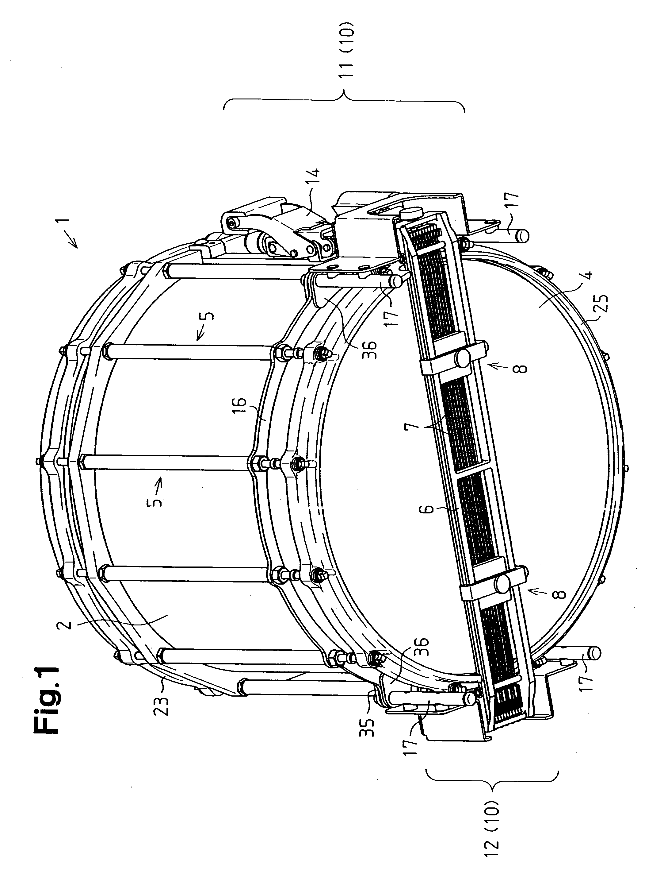
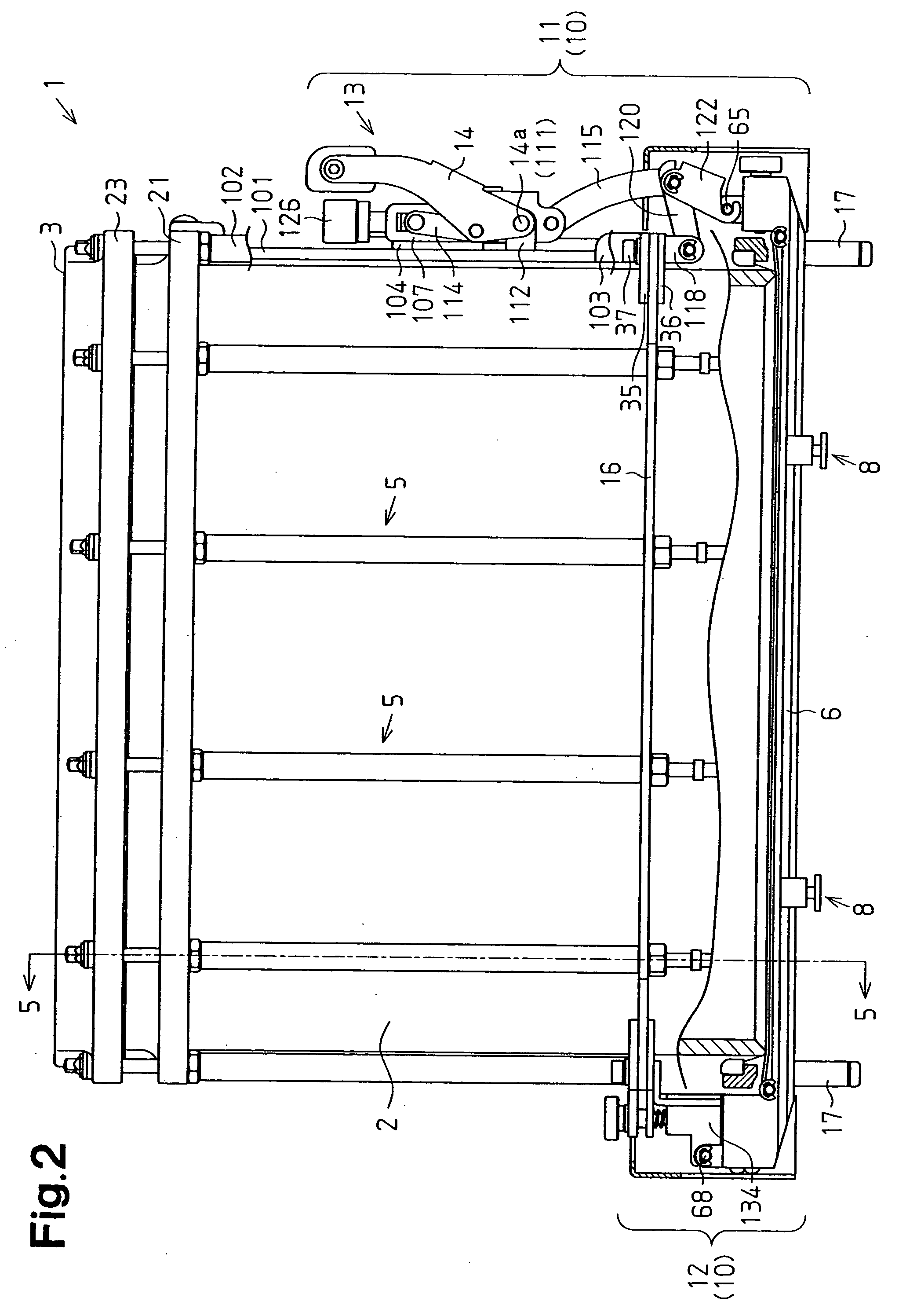
[0034] A preferred embodiment of a snare drum 1 according to the present invention will now be described with reference to FIGS. 1 through 18. The snare drum 1 includes a snare wire unit.

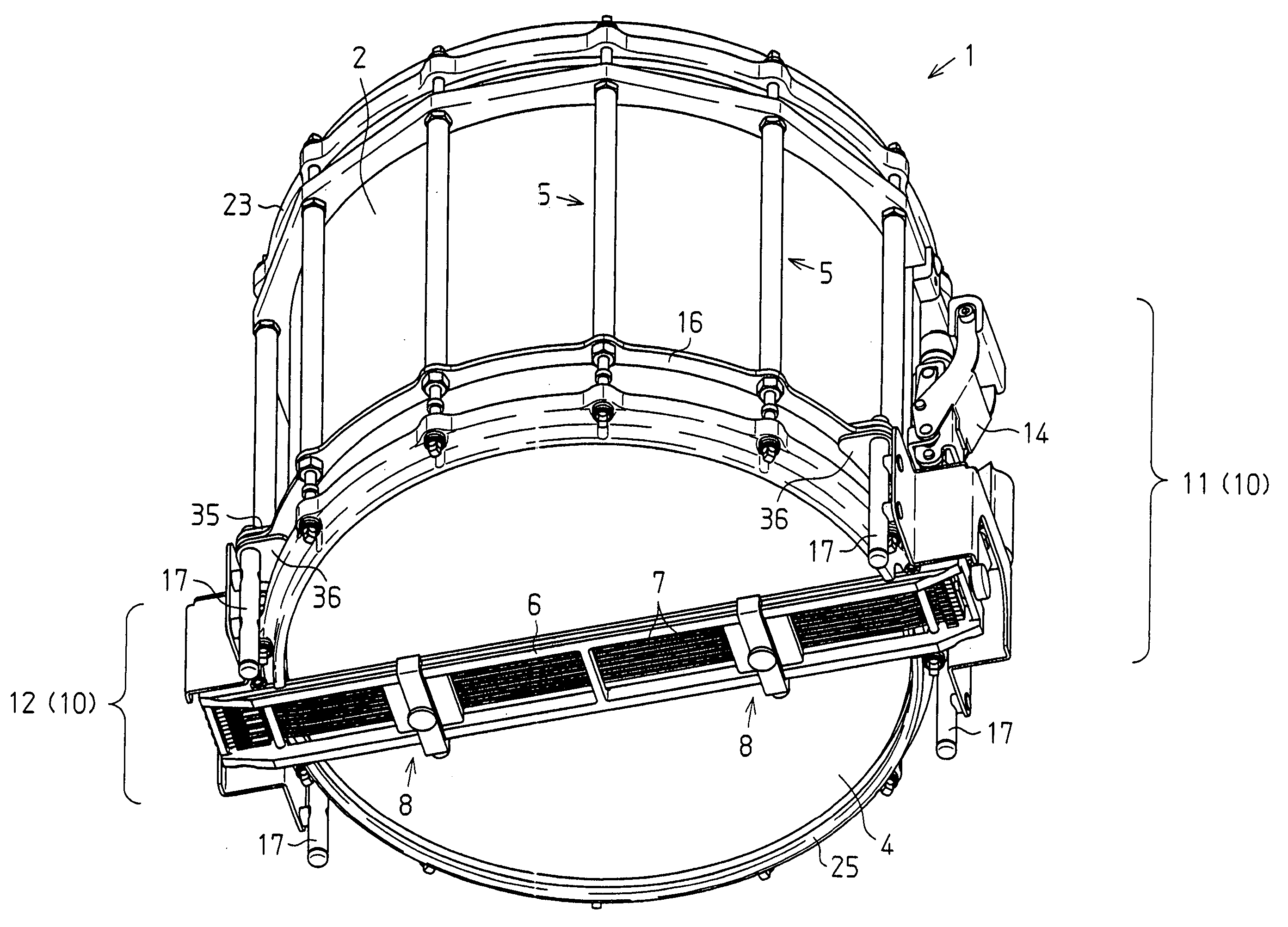
[0035] As shown in FIGS. 1 and 2, a snare drum 1 (hereafter, simply referred to as “drum”) has a cylindrical drum shell 2, the upper and lower ends of which are open. The open upper and lower ends of the drum shell 2 are closed by disk-like upper head 3 (see FIG. 2) and a disk-like lower head 4 that are fixed to the drum shell 2 by an upper hoop 23 and a lower hoop 25, respectively. A plurality of (twelve in this embodiment) head adjusters 5 for adjusting the tension applied to the upper and lower heads 3 and 4 are arranged at equal angular intervals along the peripheral wall of the drum shell 2 so as to connect the upper hoop 23 and the lower hoop 25.

[0036] A plurality of snare wires 7, which are formed from stringing, are held by a snare wire unit frame 6 and are arranged on the lower head 4 to ...


PUM


Abstract

A snare drum including a drum shell having an upper head and a lower head mounted thereon and a frame for holding a plurality of snare wires. The frame arranges the snare wires to be in contact with the lower head or to be spaced from the lower head. The snare drum includes a first latched member and a second latched member respectively located at opposite ends of the frame at an outer side the drum shell. An attachment mechanism is located on the drum shell for arranging the frame on a surface of the lower head. The attachment mechanism includes a first latching member and a second latching member arranged between the drum shell and the first and second latched members for separably latching the first and second latched members, respectively.

Description

BACKGROUND OF THE INVENTION [0001] The present invention relates to a snare drum, and more particularly, to a snare drum of a type having a plurality of snare wires held by a frame. [0002] A snare drum having a plurality of snare wires on a lower head face is known in the prior art (see U.S. Pat. No. 1,832,227). [0003]FIG. 19 is a perspective view showing a snare wire unit 211 of a first prior art example. FIG. 20 is a view of a snare drum 200 to which the snare wire unit 211 is attached, as seen from the lower side of the drum 200. As shown in FIG. 19, the snare wire unit 211 has a plurality of snare wires 201, and a right metal holder 202 and a left metal holder 203 for holding opposite ends of the snare wires 201. In the prior art snare drum 200, the metal holders 202 and 203 are respectively inserted into and fastened to a right connector 205 and a left connecter 206, which are located on a lower hoop 204 of the drum 200. The right connector 205 has an opening in its right face ...

Claims


Application Information

Patent Timeline
Patent Type & Authority Applications(United States)
IPC IPC(8): G10D13/02
CPCG10D13/025G10D13/02G10D13/18
Inventor SHIMADA, MASAHIRO
Owner HOSHINO GAKKI COMPANY LIMITED
Why Eureka
Try Eureka